EasyManua.ls Logo

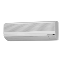
Daikin FTK35JVE9 User Manual

Daikin FTK35JVE9
410 pages
To Next Page IconTo Next Page
Page #1 background imageLoading...
Page #1 background image
Si18-201
J Series
[Applied Models]
!
!!
!Super Multi Plus : Cooling Only
!
!!
!Super Multi Plus : Heat Pump
Service
Manual

Table of Contents

Questions and Answers:

Daikin FTK35JVE9 Specifications

General IconGeneral
BrandDaikin
ModelFTK35JVE9
CategoryAir Conditioner
LanguageEnglish

Summary

Part 1 List of Function

1.1 Function List for General

Lists general functions available for various indoor unit types.

1.2 Function List for China

Details functions specific to models sold in China.

1.3 Function List for Taiwan

Details functions specific to models sold in Taiwan.

1.4 Function List for Europe

Details functions specific to models sold in Europe.

1.5 Function List for Singapore, Malaysia, Indonesia

Lists functions for units in Southeast Asian markets.

1.6 Function List for Australia

Details functions specific to models sold in Australia.

1.7 Function List for Europe

Details functions specific to models sold in Europe.

Part 2 Specifications

1.1 Outdoor Units

Provides detailed technical specifications for outdoor units.

1.2 BP Units

Lists detailed specifications for Branch Provider (BP) units.

1.3 Indoor Units (for General)

General specifications for various indoor unit types.

1.4 Indoor Units (for China)

Specifications for indoor units sold in China.

1.5 Indoor Units (for Taiwan)

Specifications for indoor units sold in Taiwan.

1.6 Indoor Units (for Europe)

Specifications for indoor units sold in Europe.

Part 3 Printed Circuit Board Connector Wiring Diagram and Name

1.1 Branch Provider Unit BPMK928B42, B43

Details connectors and wiring for BP units.

1.5 CDX25~60HAV Series, CDK25~60HAV Series

Wiring diagrams for specific indoor unit series.

1.7 FHYC35~71KV Series

Wiring diagrams for FHYC series indoor units.

1.8 FDYM60FA, FDYM03FA Series

Wiring diagrams for FDYM series indoor units.

Part 4 Main Functions Indoor Unit

1.1 Main Functions in Split Type

Details primary functions of split type indoor units.

1.2 SkyAir

Explains specific functions for SkyAir indoor units.

1.3 Cautions when SkyAir [Auto] [FAN] are used

Provides critical warnings for SkyAir auto/fan modes.

Part 5 Main Functions Outdoor Unit / BP Unit

1.1 Refrigerant System and Function of Functional Parts of Outdoor Unit

Explains the refrigerant system and key components of outdoor units.

1.2 Major Functional Parts

Details the primary functional parts of the outdoor unit.

1.3 Protective Devices, Thermistors, Sensors

Lists and explains protective devices, thermistors, and sensors.

2.1 Outdoor Unit

Specific protection devices for the outdoor unit.

2.2 BP Unit

Specific protection devices for the BP unit.

3.2 Mode Configuration

Explains how different operating modes are configured.

3.3 Standby Control at Power ON

Details the standby control logic when power is applied.

3.4 Cooling / Heating Standby Operation at Startup

Describes standby operations during startup for cooling/heating.

3.5 Equalizing Control

Explains the equalizing control process for compressor startup.

3.6 Determination of Initial Frequency

Details how the initial operating frequency is determined.

3.7 Oil Return Operation

Describes the process of oil return during operation.

3.8 Defrost Operation

Explains the defrost cycle for heating operation.

3.9 Pre-Equalization Standby Operation

Details the pre-equalization standby process.

3.10 Equalizing Control

Explains the equalizing control process.

3.11 Capacity Control

Describes how system capacity is controlled.

3.12 Peak Cut Control

Explains the peak cut control mechanism.

3.13 Freeze-Up Prevention

Details measures to prevent freezing of the indoor heat exchanger.

3.14 Gas Shortage Malfunction

Describes how gas shortage malfunctions are detected and handled.

3.15 Discharge Pipe Control

Explains control logic based on discharge pipe temperature.

3.16 Input Current Control

Details control based on input current.

3.17 Wet Protection Control I

Explains wet protection control measures.

3.18 Electric Parts Cooling and Electric Parts / Fin Temperature Control

Covers cooling of electric parts and fin temperature control.

3.19 Differential Pressure Control

Explains control based on differential pressure.

3.20 Year-Round Cooling-Only Function

Details the function for year-round cooling operation.

3.21 Nighttime Low Noise Control

Explains how noise is reduced during nighttime operation.

3.22 PI Control

Describes the PI control logic for system adjustments.

3.23 Warm-Up Function

Explains the warm-up function for the compressor.

3.24 Compressor Protection Control

Details control measures to protect the compressor.

3.25 Fan Control

Explains fan speed control logic.

3.26 Motorized Valve Control of Outdoor Unit

Details control of motorized valves in the outdoor unit.

3.27 Cooling Outdoor Unit SC Control

Explains subcooling control for outdoor units in cooling mode.

3.28 BP Unit Motorized Valve Control

Details motorized valve control for BP units.

3.29 Gas Pipe Isothermal Control in Cooling Operation

Explains isothermal control for gas pipes in cooling.

3.30 SH Control in Cooling Operation

Details superheat control for cooling operation.

3.31 SC Control in Heating Operation

Explains subcooling control for heating operation.

3.32 Heat Exchanger Isothermal Control in Heating Operation

Describes isothermal control for heat exchangers in heating.

3.33 BP Unit Motorized Valve Control in High Discharge Pipe Temperature

Details BP unit valve control based on high discharge pipe temperature.

3.34 Inter-BP Units Heating Heat Exchanger Isothermal Control

Explains isothermal control for heat exchangers between BP units in heating.

3.35 Inter-BP Units Gas Pipe Isothermal Control

Explains isothermal control for gas pipes between BP units.

3.36 BP Unit Motorized Valve Control by Target Discharge Pipe Temperature

Details BP unit valve control based on target discharge pipe temperature.

3.37 4-Way Valve Operation

Explains the operation and security of the 4-way valve.

3.38 JIS Mode

Details the JIS mode for capacity deviation minimization.

3.39 Pump Down Operation

Explains the pump down operation procedure.

3.40 Protection Control of SkyAir Indoor Units

Details protection controls for SkyAir indoor units.

Part 6 Flow of Refrigerant

1.2 Standby Operation (Cooling)

Illustrates refrigerant flow during standby in cooling mode.

1.3 Equalizing Control (Cooling)

Shows refrigerant flow during equalizing in cooling.

1.4 Oil Return Operation (Cooling)

Illustrates refrigerant flow during oil return in cooling.

1.5 Low Outside Air Temperature Cooling

Shows refrigerant flow during cooling at low outside temperatures.

1.6 All-Room Operation (Cooling)

Illustrates refrigerant flow for all rooms operating in cooling.

1.7 Multi-Room Operation (No Surplus Refrigerant) (Cooling)

Shows refrigerant flow for multi-room cooling without surplus refrigerant.

1.8 Multi-Room Operation (Cooling) (with Surplus Refrigerant)

Illustrates refrigerant flow for multi-room cooling with surplus refrigerant.

1.9 1-Room Operation — Indoor Unit with Large Capacity (Cooling)

Shows refrigerant flow for single large-capacity indoor unit cooling.

1.10 1-Room Operation — Indoor Unit with Small Capacity (2.5 kW) (Cooling)

Illustrates refrigerant flow for single small-capacity indoor unit cooling.

1.11 Standby Operation (Heating)

Shows refrigerant flow during standby in heating mode.

1.12 Equalizing Control (Heating)

Illustrates refrigerant flow during equalizing in heating.

1.13 Oil Return Operation (Heating)

Shows refrigerant flow during oil return in heating.

1.14 Defrost Operation

Illustrates refrigerant flow during defrost operation.

1.15 All-Room Operation (Heating)

Shows refrigerant flow for all rooms operating in heating.

1.16 Multi-Room Operation (with non-Operating Room Unit) (Heating)

Illustrates refrigerant flow for multi-room heating with non-operating units.

1.17 Multi-Room Operation (Heating)

Shows refrigerant flow for multi-room heating.

1.18 1-Room Operation — Indoor Unit with Large Capacity (Heating)

Illustrates refrigerant flow for single large-capacity indoor unit heating.

1.19 1-Room Operation — Indoor Unit with Small Capacity (2.5 kW) (Heating)

Shows refrigerant flow for single small-capacity indoor unit heating.

Part 7 Operations

1.1 Wireless Remote Controller

Explains the features of the wireless remote controller.

1.2 Wired Remote Controller

Details the features and operation of the wired remote controller.

Part 8 Operating Test

1.2 Test Operation Switch

Explains the function and usage of the test operation switch.

1.3 Pump Down Operation Switch

Details the pump down operation switch functionality.

1.4 Record of the Installation Position

Instructions for recording installation positions.

2.2 Group Number Setting for Central Remote Control

Explains how to set group numbers for central control.

2.3 Interface Adaptor for Room Airconditioner <KRP928A1S>

Details the interface adaptor for room air conditioners.

2.4 Precautions: For RMK140J / RMX140J Outdoor Unit Users

Provides essential precautions for users of specific outdoor units.

Part 9 Service Diagnosis

1.1 Troubleshooting with the Operation Lamp

Explains how to troubleshoot using the operation lamp indicator.

1.2 Service Check Function

Details the service check function for diagnostics.

1.3 Code Indication on the Remote Controller

Lists error codes displayed on the remote controller.

1.5 Troubleshooting Detail

Provides detailed troubleshooting steps for specific issues.

2.1 The INSPECTION/TEST Button

Explains the function of the inspection/test button.

2.2 Self-Diagnosis by Wired Remote Controller

Details self-diagnosis using a wired remote controller.

2.3 Fault Diagnosis by Wireless Remote Controller

Explains fault diagnosis using a wireless remote controller.

2.4 Troubleshooting by LED on the Indoor Unit’s

Troubleshooting based on indoor unit LED indicators.

2.5 Troubleshooting by Remote Controller Display / LED Display

Troubleshooting using remote controller display and LEDs.

2.6 Troubleshooting Detail

Detailed troubleshooting steps for SkyAir units.

3.1 The Unit Runs but Doesn’t Cool (Heat) the Room

Troubleshooting steps when the unit doesn't cool or heat.

3.2 7 Seg. Display on the Outdoor P. C. Board

Interpreting the 7-segment display on the outdoor PC board.

3.3 Troubleshooting Detail

Detailed troubleshooting for outdoor unit issues.

3.4 How to Check

Provides methods for checking specific components.

4.1 PCB Parts Layout

Identifies parts on the BP unit PCB.

4.2 LED On Branch Provider Unit (Diagnosis LEDs)

Explains diagnosis using LEDs on the branch provider unit.

Part 10 Removal Procedure

1.1 Installation of Indoor Unit

Steps for installing indoor units.

1.2 Opening of Electrical Box Cover and Removal of PCB Mount

Steps to access and remove the PCB mount.

1.3 Removal of Motorized Valve

Procedure for removing motorized valves.

1.4 Removal of Thermistor

Steps for removing thermistors.

2.1 Removal of Outer Panels

Steps to remove outer panels of the outdoor unit.

2.2 Removal of PCB and Electrical Box

Procedure for removing the PCB and electrical box.

2.3 Removal of Propeller Fans and Fan Motors

Steps to remove propeller fans and motors.

2.4 Removal of Thermistor

Procedure for removing thermistors from the outdoor unit.

2.5 Removal of Motorized Valve

Steps to remove motorized valves from the outdoor unit.

2.6 Removal of Sound Insulation

Procedure for removing sound insulation.

2.7 Removal of Compressor

Steps for removing the compressor.

2.8 Removal of 4-way Valve

Procedure for removing the 4-way valve.

3.1 Refer following table for indoor unit removal procedure

Table guiding indoor unit removal procedures.

Part 11 Cautions before Operation

1.1 Outdoor Unit

Installation precautions specific to the outdoor unit.

1.2 BP Unit

Installation precautions specific to the BP unit.

2.1 Outdoor Unit

Wiring precautions for the outdoor unit.

2.2 BP Unit

Wiring precautions for the BP unit.

2.3 Outdoor Unit Rotary Switch Setting

Instructions for setting the outdoor unit rotary switches.

3.1 Explanation for FTK(X)25/35J Series

Explanations specific to FTK/FTX 25/35J series.

3.2 Explanation for FTK(X)50/60H and CDK(X)25~60H Series

Explanations for FTK/CDK 50/60H series.

Part 12 Appendix

1.1 Outdoor Units

Piping diagrams for outdoor units.

1.2 BP Units

Piping diagrams for BP units.

1.3 Indoor Units

Piping diagrams for indoor units.

2.1 Outdoor Units

Wiring diagrams for outdoor units.

2.2 BP Units

Wiring diagrams for BP units.

2.3 Indoor Units

Wiring diagrams for indoor units.

Related product manuals