Installation and operation manual
8
FWEC1
Standard electronic controller
FC66002763
ELECTRONIC BOARD (SEE FIGURE 3)
Where:
CI12
DI1-2 Common
DI1
Remote cooling/heating
DI2
Remote On/Off
L
Phase
N
Neutral
PE
Ground
SA
Remote air sensor
SW
Water sensor
V0
-
V1
Low speed.
V2
Medium speed
V3
High speed
Vc
Valve
Vh
Heater valve/ Heater/extra-low speed
NB
■ For power connections use cable w/ cross section size of 2
mm2
■ For digital inputs used AWG 24 cable
■ For sensor extensions use AWG 24 shielded cable
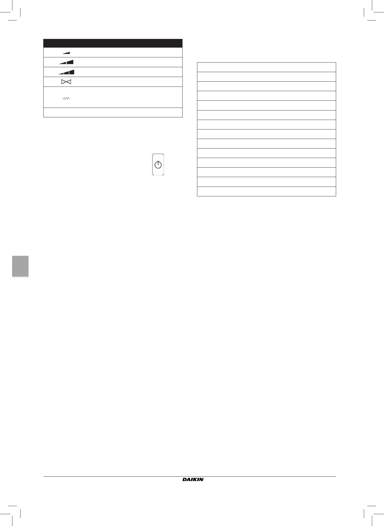
Symbol Actuation Terminals
Min. speed N-V1
Med. speed N-V2
Max. speed N-V3
Valve N-Vc
Heating element
Second valve
Extra low speed
N-Vh
no symbol no active outlet
The electronic controller outputs can be checked one by
one either by observing the respective component (valve,
fan..) or verifying whether a voltage of 230 V is present at the
corresponding terminals.
■ To exit the self-diagnosis procedure press
(after a
few minutes the thermostat will automatically exit in any
case).