Installation and operation manual
10
FWEC1
Standard electronic controller
FC66002763
WIRING DIAGRAMS
Unit table/Diagrams
…..
Electrical connections to be made by installer
BU
Blue (Med. speed)
BK
Black (Max. speed)
BN
Brown
CI12
Digital input common
CN
Terminal board
DI1
Remote Heat/Cool Digital Input
DI2
Remote On/Off Digital Input
EXT
External auxiliary contact
F
Fuse (not supplied)
GN
Green
GY
Grey
IL
Circuit breaker (not supplied)
IPM
Circuit board for UTN units
KP
Circuit board to control 4 indoor units
L
Phase
M
Fan motor
MS
Flap microswitch
N
Neutral
PE
Ground
RHC
Heating/Cooling remote selecting switch
RE
Heating element
RD
Red (Min. speed)
SA
Air sensor
SC
Wiring box
SW
Water sensor
TSA
Automatic safety thermostat
TSM
Safety fuse
Vo
-
V1
Min. speed
V2
Med. speed
V3
Max. speed
VC
Solenoid valve - Cooling
VH
Solenoid valve - Heating
VHC
Solenoid valve –Cool/Heat.
WH
White (common)
YE
Yellow
KR
Heating element relay
INSTALLATION OF WALL-MOUNTED
CONTROLLER
For wall mounting of the controller it is advisable to use
an electric box behind the controller to accommodate the
cables.
NB: Prior to installation, carefully remove the protective fi lm
from the display; removal of the fi lm may cause some
dark streaks to appear on the display but these will
disappear after a few seconds and are not signs of a
controller defect.
Instructions for installation:
■ Remove the fastening screw of the controller (see fi gure 4).
■ If a 503 electrical enclosure is used, pass the cables
through the slot at the bottom of the controller and use
the holes provided for fastening. (see fi gure 5).
■ Otherwise, in the wall where you wish to mount the control-
ler, drill holes to match up with the fastening slots (5x8mm)
on the base of the controller; pass the cables through the
slot on the base and screw it to the wall (previously drilled).
(see fi gure 6).
■ Make the electrical connections to the indoor unit termi-
nal block as per the wiring diagram.
■ Close the controller with the screw provided.
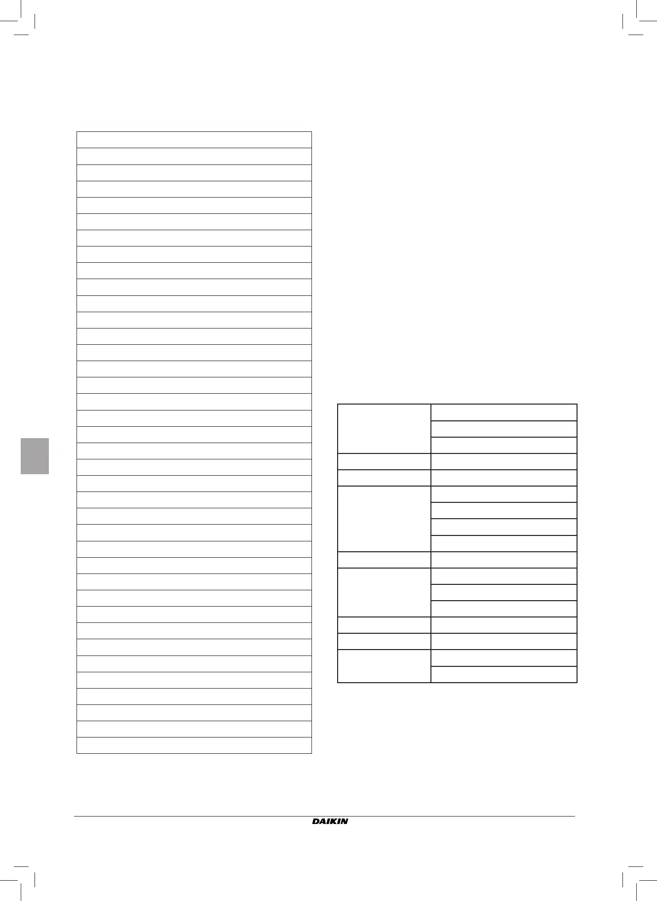
TECHNICAL DATA
Power supply
90-250Vac 50/60Hz
Electrical input 8W
Protection fuse 500mA delayed
Operating temp. Range 0-50°C
Storage temp. Range -10-60°C
Relay
NO 5A @ 240V (Resistive)
insulation: coil-contact distance 8 mm
4000V coil-relay dielectric
Max ambient temperature 105°C
Connectors 250V 10A
Digital inputs
Clean contact
Closing current 2mA
Max. closing resistance 50 Ohm
Analog inputs Temperature sensors
Power outputs Relay (see above)
Temperature sensors
NTC sensors 10K Ohm @25°C
Range -25-100°C