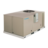
Do you have a question about the Daikin Maverick I MPSA07D and is the answer not in the manual?
Details warnings and precautions related to installation, operation, and potential hazards.
Covers power supply requirements, branch circuit wiring, and wire size determination.
Details power supply requirements, voltage checks, and branch circuit disconnect installation.
Presents the electrical wiring diagram for specific unit models and configurations.
Electrical wiring diagram for DDC-controlled units of specific models.
Wiring diagram for electromechanical units with Two-Speed SAF Gas Heat.
Wiring diagram for DDC-controlled units with Two-Speed SAF Gas Heat.
Wiring diagram for electromechanical units with Two-Speed SAF Cooling Only.
Wiring diagram for DDC-controlled units with Two-Speed SAF Cooling Only.
Wiring diagram for electromechanical units with Constant Volume.
Wiring diagram for DDC-controlled units with Constant Volume Gas Heat.
Wiring diagram for electromechanical units with Constant Volume Cooling Only.
Wiring diagram for electromechanical units with Constant Volume Cooling Only.
Wiring diagram for electromechanical units with Two-Speed SAF Cooling Only.
Wiring diagram for electromechanical units with Two-Speed SAF Cooling Only.
Wiring diagram for DDC-controlled units with Constant Volume Cooling Only.
Wiring diagram for DDC-controlled units with Constant Volume Cooling Only.
Wiring diagram for DDC-controlled units with Two-Speed SAF Cooling Only.
Wiring diagram for DDC-controlled units with Two-Speed SAF Cooling Only.
Wiring diagram for DDC-controlled units with HGRH.
Wiring diagram for DDC-controlled units with HGRH.
Airflow performance charts for the MPS 012D model, detailing CFM, RPM, and W at different static pressures.
Side airflow performance data for the MPS 012D model, including correction factors and component air resistance.
Explains the two-stage integrated direct spark ignition control and furnace operation sequences.
Details the function and safety warnings associated with the manual reset over-temperature controls.
Discusses the supply air high temperature limit cut-off and its safety implications.
Detailed steps for furnace section maintenance, including cleaning heat exchangers and turbulators.
A chart listing cooling symptoms, possible causes, and recommended remedies.
A flowchart detailing troubleshooting steps for furnace ignition and operation issues.
| Brand | Daikin |
|---|---|
| Model | Maverick I MPSA07D |
| Category | Air Conditioner |
| Language | English |


