OM 752-4 14 www.DaikinApplied.com
desCrIptIon of operatIon
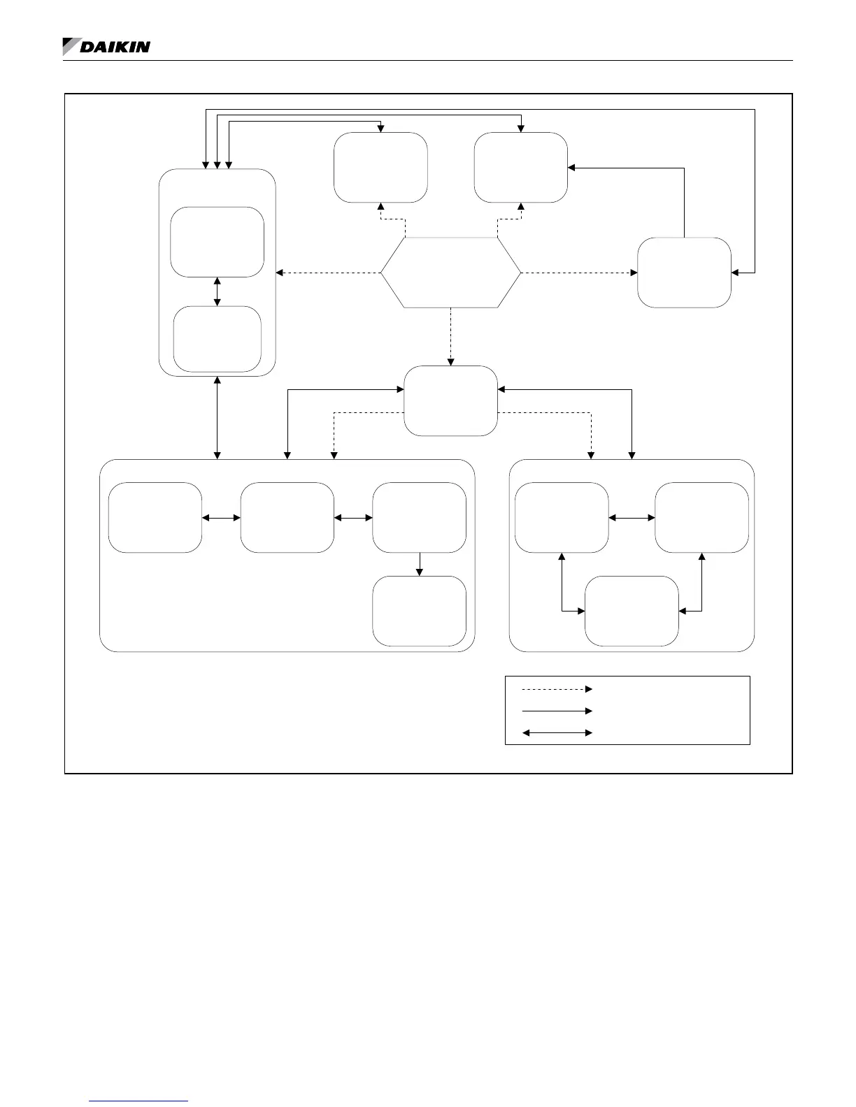
Figure 6: Complete UVC—state diagram
LUI Input
Network Input
AUTO
Mode
OFF
Mode
(State 9)
NIGHT PURGE
Mode
(State 8)
FAN ONLY
Mode
(State 10)
EMERGENCY HEAT
Mode
CANT HEAT
Mode
(State 13)
FULL HEAT
Mode
(State 7)
HEAT Mode
HEAT
Mode
(State 5)
LOW LIMIT
Mode
(State 14)
CANT HEAT
Mode
(State 11)
COOL Mode
ECON
Mode
(State 3)
CANT COOL
Mode
(State 12)
DA HEAT
Mode
(State 4)
LOW LIMIT
Mode
(State 15)
Manual/Forced Transition
One-way Automatic Transition
Two-way Automatic Transition
UVC Unit Modes
The UVC provides several “normal” modes of unit operation. These include: Off, Night
Purge, Fan Only, Emergency Heat, Auto, Heat, and Cool.
Normal UVC modes can contain a single state or several states depending upon the
functionality required for each particular mode. Each UVC state is assigned a number,
which can be very helpful when trying to understand which state is currently active
within the UVC. To view the current UVC state number, use the keypad/display.