www.DaikinApplied.com 35 OM 752-4
desCrIptIon of operatIon
Floating-Point Actuator Auto-Zero, Overdrive and Sync
The UVC at power-up auto-zeros all oating-point actuators (OA damper) before going
into normal operation to ensure proper positioning. During auto-zero, the unit remains
off. The actuators all open approximately 30% and then are driven full closed. The
overdrive feature then is used to continue forcing the actuators closed for one full
stroke period. Once the zeroing process is complete, normal unit operation begins.
The UVC is congured such that whenever a oating-point actuator is commanded to
go to 0% or 100%, the UVC overdrives the actuator one full stroke period past the 0%
or 100% position to ensure proper positioning.
Additionally, the UVC is congured to sync all oating-point actuators once every six
hours of operation. To do this, the UVC forces the actuator to the closest rail position
(0% or 100%), uses the overdrive feature, and then returns to the required position. For
example, if the actuator is at 20% when the six-hour limit is reached, the UVC then forces
the actuator to 0%, overdrive for one full stroke and then returns to the 20% position.
External Binary Inputs
The UVC is provided with three binary inputs that provide the functions described
below.
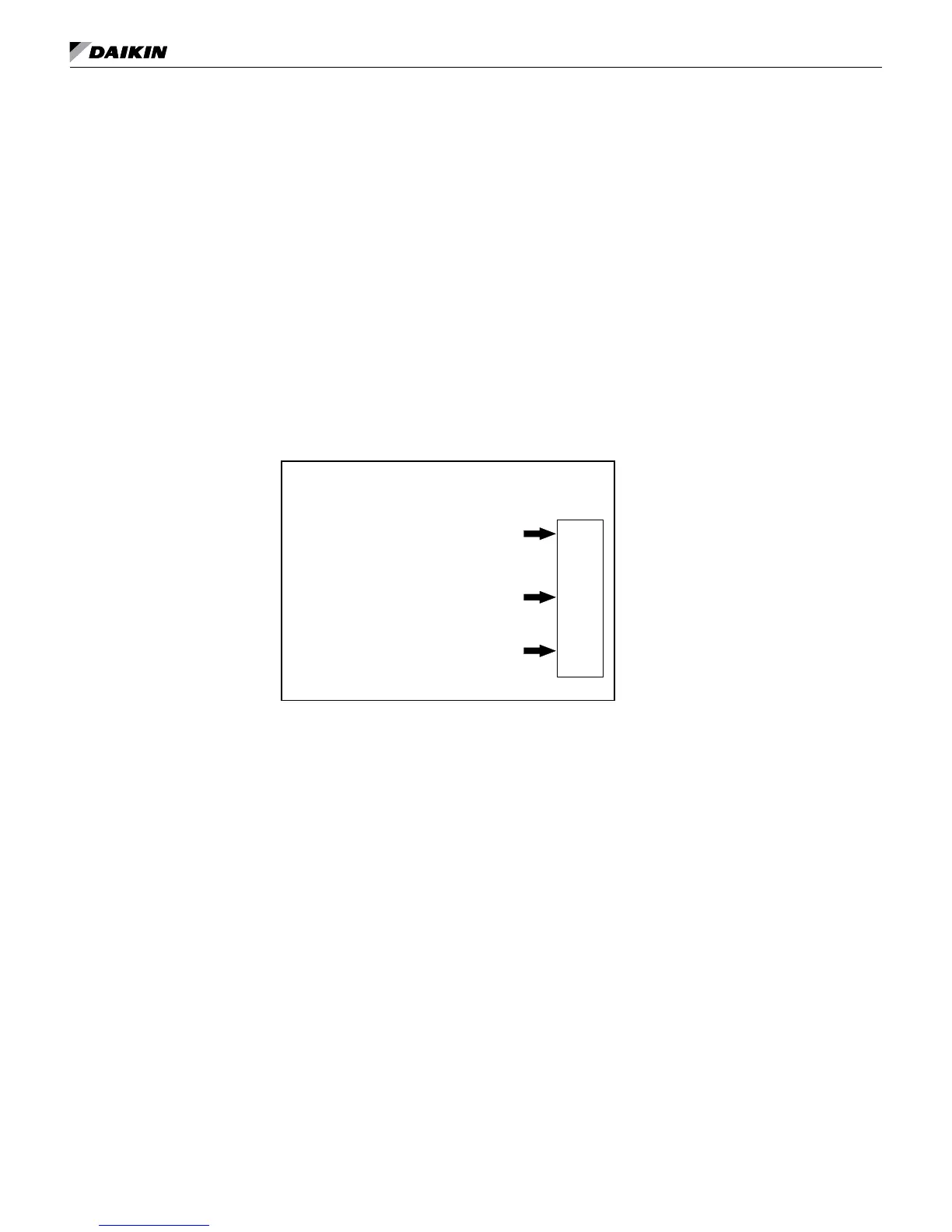
Figure 22: Binary inputs
Binary Inputs
3 sets of dry contacts to signal UVC
Input 1: Unoccupied (default)
Input 2: Remote shutdown
Input 3: Ventilation lockout (default)
or
Exhaust interlock system
These inputs each allow a single set of dry contacts to be used as a signal to the UVC.
Multiple units can be connected to a single set of dry contacts. For wiring examples,
see MicroTech II Unit Ventilator Controller IM 747.
Note: Not all of the functions listed can be used at the same time. The UVC is provided with
conguration parameters that can be adjusted to select which function is used for these
inputs where multiple functions are indicated below.
External Binary Input 1
This input can be used only as an unoccupied signal.
Unoccupied Input Signal
This input allows a single set of dry contacts to be used to signal the UVC to go into
unoccupied or occupied mode. When the contacts close, the UVC goes into unoc-
cupied mode. When the contacts open, the UVC goes into occupied mode. Additional
variables can effect occupancy mode and override this binary input. See "Occupancy
Modes" on page 24.
External Binary Input 2
This input can only be used for remote shutdown.
Remote Shutdown Input Signal
This input allows a single set of dry contacts to be used to signal the UVC to go into
shutdown mode. When the contacts close (shutdown), the UVC goes into shutdown
mode. When the contacts open. the UVC returns to normal operation.