11
OM 1364-1
WWW.DAIKINAPPLIED.COM
OPERATION
board conguration switches SW1-SW4 and the corresponding
stage 1 CFM. If a two stage thermostat is used, a further demand
for cooling will change (increase) the CFM output of the EC fan
motor.
When the room setpoint conditions are satised, the compressor
will shut o and the fan will either shut o (fan switch “AUTO”)
or continue to run (fan switch “ON” or conguration switch SW2
is OFF). The compressor minimum o timer of 360 seconds will
start.
If additional capacity is needed on two stage or two compressor
units, the unit will initiate stage 2 heating. When the room
setpoint conditions are satised, the stage 2 compressor will shut
o rst followed by the stage 1 compressor.
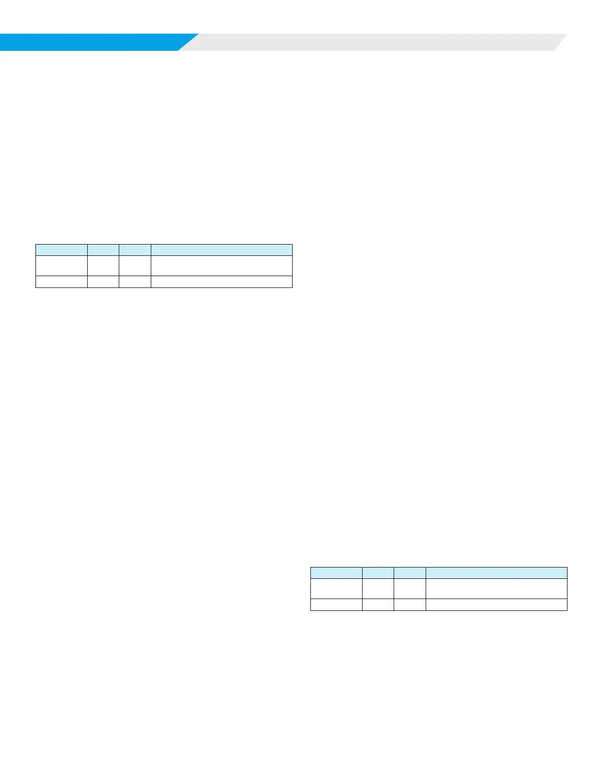
Heating
LED Activity Type Color Description
1 Flash Mode Green
No Call for Heating/Cooling/
Dehumidication
3 Flash Mode Green Call for Heating
The compressor minimum o timer, and random start timer must
expire before the compressor will be energized. On a call for
1st stage heating, from a thermostat or network setpoint, the H6
output on the MT2300 board is activated to open the motorized
valve to allow water ow through the heat exchanger. The fan
starts immediately (unless it is already on through activation of
the G terminal by the thermostat fan switch “ON” or a wall sensor
command) at low CFM. The compressor starts after 60 seconds
to make sure the motorized valve has fully open for proof of
water ow and the fan CFM output increases. The compressor
minimum on timer of 180 seconds starts. The reversing valve will
energize 5 seconds after the compressor starts. The fan output is
now determined by the MT2310 I/O board conguration switches
SW1-SW4 and the corresponding stage 1 CFM. If a two stage
thermostat is used, a further demand for heating will change
(increase) the CFM output of the EC fan motor.
When the room setpoint conditions are satised, the compressor
will shut o and the fan will either shut o (fan switch ”AUTO”) or
continue to run (fan switch “ON” or conguration switch SW2 is
OFF). The compressor minimum o timer of 360 seconds starts.
If additional capacity is needed, on two stage or two compressor
units, the unit will initiate stage 2 cooling. When the room setpoint
conditions are satised, the stage 2 compressor will shut o rst
followed by the stage 1 compressor.
Boilerless Electric Heat Mode
Units equipped with the boilerless electric heat option include
an entering water temperature sensor. On a call for heating
the fan starts immediately (unless it is already enabled through
activation of the G terminal from the thermostat fan switch “ON”
or a wall sensor command.) at “FAN ONLY” setting. The H6
output on the MT2300 board is activated to open the motorized
valve allowing water ow thru the heat exchanger. If the entering
water temperature is below set point, (55°F standard units or
28°F for geothermal units), the MT2300 controller will disable the
compressor, increase the fan speed to electric heat CFM and
energize a 24VAC output to the electric heat control circuit. When
the room setpoint conditions are satised, the electric heater will
turn o and the fan will either cycle o (fan switch “AUTO”) or
continue to operate (fan switch “ON” or conguration switch SW2
is OFF). If the entering water temperature is above setpoint, the
unit will operate in compressor heating mode. The setpoints are
adjustable by the BAS.
Supplemental Electric Heat Mode
On a call for supplemental electric heat (W3) or BAS setpoint, the
compressor will continue to operate, the fan speed will increase
to the electric heat setting and electric heating will energize.
For units equipped with two stages of electric heat, W4 or BAS
setpoint will turn on second stage of electric heat.
Emergency Electric Heat Mode
On a call for emergency heat, the fan will energize at its “electric
heat” setting. When the room setpoint conditions are satised,
electric heat will be de-energized. The fan will operate according
to its “FAN ONLY” setting when enabled, for continuous fan
operation. If fan cycling is enabled, the fan will turn o once room
setpoint conditions are satised. A 24V control signal to TB1-W4
from the thermostat or BAS will initiate a call for stage 2 electric
heat.
Hydronic Heat Mode
This mode requires optional hydronic heat factory installed on
vertical units. A hydronic coil, 3-way valve and entering water
temperature sensor are included with this option. The purpose of
this mode is to satisfy the heating demand by using the elevated
loop water temperature between 90°F and 120°F.
On a call for 1st stage heating with entering loop water above
90°F, the H6 output on the MT2310 I/O expansion module is
activated to open the motorized valve diverting water ow to the
hydronic coil. The fan starts after 30 seconds (unless it is already
activated by the thermostat or room sensor). The fan output is
determined by the MT2310 I/O expansion module conguration
switch. When the room setpoint conditions are satised, the
3-way valve will close and the fan will either shut o (fan switch
”AUTO”) or continue to run (fan switch “ON” or conguration
switch SW2 is OFF). When entering loop water temperature is
below 90°F, standard heating operation resumes.
Smart Dehumidication (Hot Gas Reheat)
LED Activity Type Color Description
1 Flash Mode Green
No Call for Heating/Cooling/
Dehumidication
6 Flash Mode Green Call for Dehumidication
This mode requires optional hot gas reheat and a humidistat
input to the MT2310 I/O expansion module. This option also
utilizes airow management. If the space cooling temperature
setpoint is satised, but the humidity is above the space humidity
setpoint, the dehumidication mode is activated. The return air
temperature must be 68°F or greater.
On a call for smart dehumidication, the fan will energize at its
fan only setting, the pump will energize. After the 60 second
ow timer and the compressor minimum o timer expire (360