fAULT MODES
MICROTECH 2300 UNIT CONTROLLERDAIKIN APPLIED
20
Status LED Indication
The MT2300 and the MT2310 boards each have a three-color
status LED that provide operational mode and alarm notication.
Mode LED ashes have an ON/OFF interval of 250ms ON and
750ms OFF between cycles. Fault LED ashes have an ON/
OFF interval of 250ms ON and 1.5 second OFF between cycles.
Rapid LED ashes are ON/OFF at 150ms intervals with no
interval cycle.
Table 7: Room sensor status LED
LED On Time (Sec) LED O Time (Sec) Operating Mode
0.5 0.5
Alarm Condition or Network
“Wink” Operation Active
0.0 Continually Bypass Mode is Active
0.5 5.5 Unoccupied Mode
5.5 0.5 Standby Mode
Continually 0.0 Occupied Mode
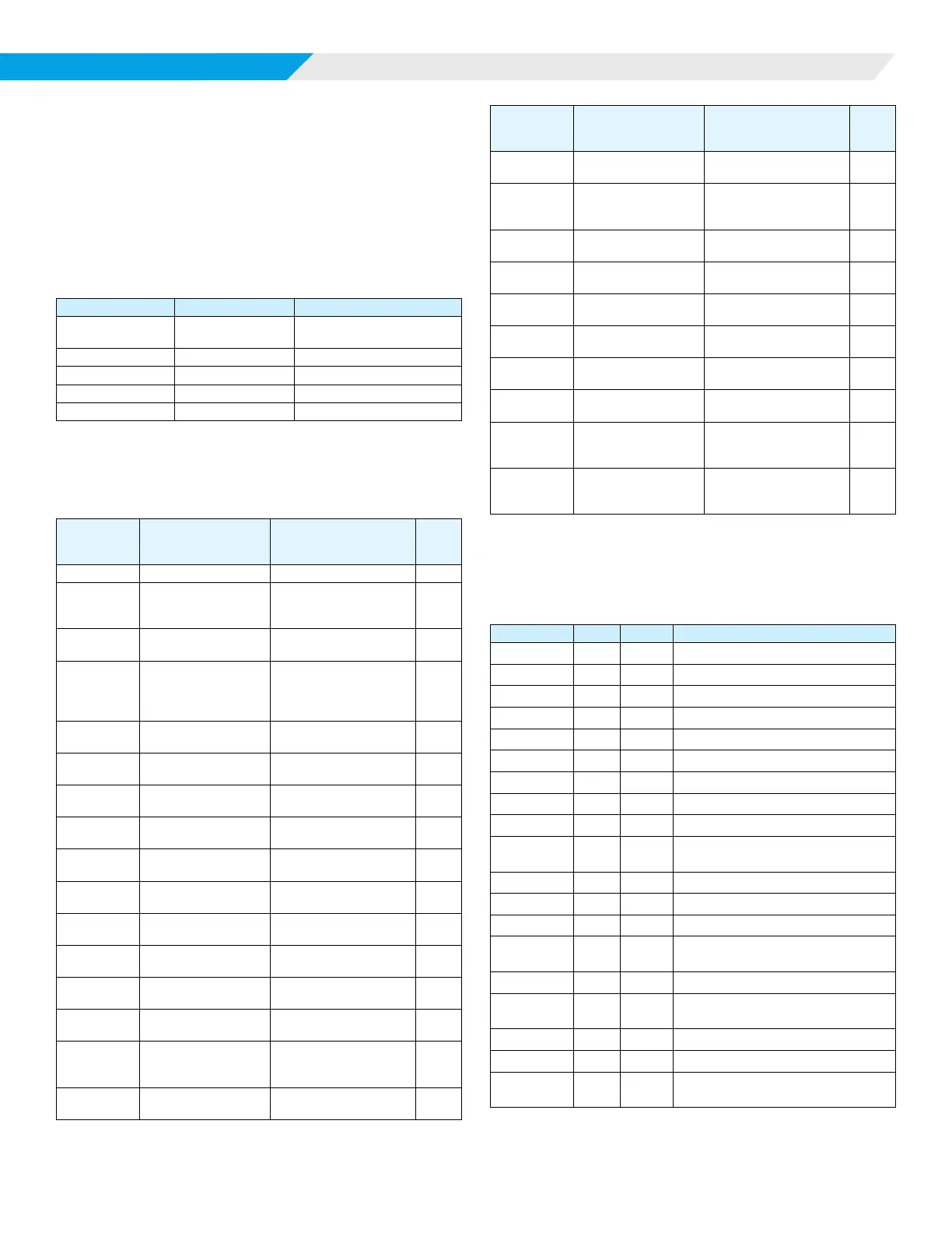
Faults and Modes
Table 8: Priority level of faults and modes, and resets
Alarm
Enumeration
(BACnet)
Fault Indication Reset
1
1 No Alarm Normal operation NA
2
MT2310 Communica-
tion Failure
Single compressor unit
with SW 8 set to ON
position
A
3 Incompatible Software
Incorrect Software Part
or Version Numbers
P
4 Invalid Conguration
Base & IO Exp Appli-
cation Mismatch or
MT2310 detected but not
required (SW 8)
P
5 A2L Alarm
A2L refrigerant leak
detected
A
6 A2L Error - Power
A2L mitigation control is
not powered
A
7
Compressor Low
Voltage
"Brownout" condition
exists
A
8
Comp 1 High
Pressure
Compressor 1 high pres-
sure switch opened
T,N
9
Comp 2 High
Pressure
Compressor 2 high pres-
sure switch opened
T,N
10 Comp 1 Low Pressure
Compressor 1 low pres-
sure switch opened
T,N
11 Comp 2 Low Pressure
Compressor 2 low pres-
sure switch opened
T,N
12
Comp 1 Suction Temp
Sensor
Compressor 1 suction
temp sensor failure
N
13
Comp 2 Suction Temp
Sensor
Compressor 2 suction
temp sensor failure
N
14
Leaving Water Temp
(LWT) Sensor
LWT sensor not present
(SW 4 = ON)
N
15
Freeze Fault Detect
(FFD)
LWT sensor temp below
freeze setpoint
(SW 4 = ON)
T,N
16
Comp 1 Low Suction
Temp (ST1)
ST1 sensor temp below
minimum setpoint
A,T,N
2
Alarm
Enumeration
(BACnet)
Fault Indication Reset
1
17
Comp 2 Low Suction
Temp (ST2)
ST2 sensor temp below
minimum setpoint
A,T,N
2
18 A2L Error - Sensor
A2L sensor lost com-
munication or reported
failure
A
19
Control Temp Sensor
Failure
Room Temp and Return
Air Temp sensor failures
N
20
Entering Water Temp
(EWT) Sensor Failure
EWT sensor reading "out
of range"
N
21
Room Temp Sensor
Failure
Room temp sensor read-
ing "out of range"
N
22
Return Air Temp Sen-
sor Failure
RAT sensor reading "out
of range"
N
23
Space RH Sensor
Failure
Space RH sensor read-
ing "out of range"
N
24
Low Entering Water
Temp (EWT)
EWT sensor reading
below minimum setpoint
A
25 Condensate Overow
Condensate overow
sensor indicates water
present
A,N
26
Waterside Economiz-
er (WSE) Low Temp
WSE temp sensor
reading below minimum
setpoint
A
NOTE 1: “A” = Auto Reset, “T” = Tenant Override Button Reset, “N” = Network
Reset, “P” = power cycle only
NOTE 2: Low suction temperature faults have “Intelligent Reset” logic - 3 faults in
a 24 hour period disables the auto reset function.
Table 9: MT2300 Unit Controller Status LEDs
LED Activity Type Color Description
Steady ON Fault Yellow MCU Not Programmed
Steady ON Fault Red MCU Hardware Failure
1 Flash Fault R–Y–G Invalid Conguration
2 Flash Fault R–Y–G Incompatible Software
1 Flash Fault R–Y I/O Exp Board Communications Fail
1 Flash Mode G–Y Service / Test Mode Active
Rapid Flash Fault Red A2L Mitigation – Refrigerant Leak
1 Flash Fault Red Compressor 1 High Pressure
2 Flash Fault Red Compressor 1 Low Pressure
3 Flash Fault Red
Compressor 1 Suction Temp Sensor
Fail
4 Flash Fault Red Compressor 1 Low Suction Temp
5 Flash Fault Red Compressor 2 High Pressure
6 Flash Fault Red Compressor 2 Low Pressure
7 Flash Fault Red
Compressor 2 Suction Temp Sensor
Fail
8 Flash Fault Red Compressor 2 Low Suction Temp
9 Flash Fault Red
A2L Mitigation – Control Board With-
out Power
10 Flash Fault Red Compressor 1 High Discharge Temp
11 Flash Fault Red Compressor 2 High Discharge Temp
Rapid Flash Mode Yellow
A2L Mitigation – Refrigerant Sensor
Fail