9
OM 1364-1
WWW.DAIKINAPPLIED.COM
fUNCTIONALITy
Control Outputs
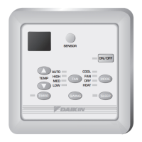
• The thermostat alarm output: Will be energized when
there are fault conditions presently active. Without any fault
conditions active, the alarm output shall be de-energized.
When energized the onboard relay closes the connection
between TB4 ALM and COM. For a 24VAC output from
ALM, connect a 24VAC source to COM.
• Isolation Valve / Pump Request [IV/PR (H6)]: is selectable
to be energized when the compressor is o (normally
closed), or when the compressor is on (normally open), by
moving the wire lead to the appropriate terminal.
Figure 4: TB4, H5, and H6 Terminals on MT2300 Board
R
H7
H8
H1
LED
FM
SP
RM
GND
LED
FM
SP
RM
GND
TB3
TB2
TB1
E
E
U
U
W2
W1
Y2
Y1
G
C
R
W2
W1
Y2
Y1
G
C
MT2300
PART# 910384405
H3
10
9
8
7
6
5
4
3
2
1
H4
RY/FAN_HIGH
RY/FAN_EN
RY/PUMP
Figure 5: Compressor Relay Terminals on MT2300 Board
H7
H8
H1
H1
LEDLED FMFM SPSP RMRM GNDGND
LED
FM
SP
RM
GND
TB3
TB2
TB1
E
E
U
U
U
W2W2 W1W1 Y2Y2 Y1Y1 GG CC
R
W2
W1
Y2
Y1
G
C
MT2300
PART# 910384405
H3
10
9
8
7
6
5
4
3
2
1
H4
RY/FAN_HIGH
RY/FAN_EN
RY/PUMP
• Compressor Relay: Line or low voltage output used to
control compressor. (On/O)
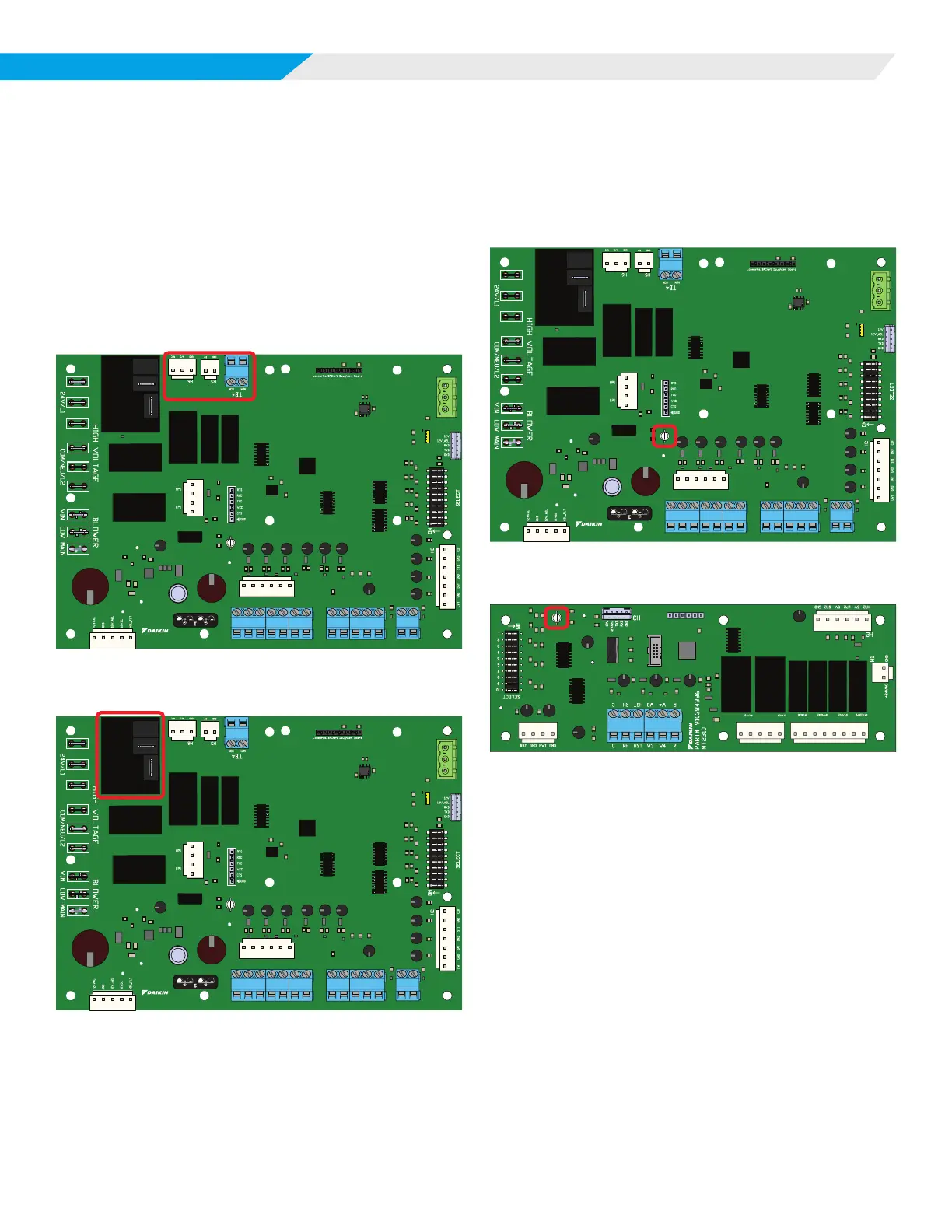
LED Indicators
When the unit controller or I/O boards are communicating a
certain fault or mode, the LED indicator will ash a designated
pattern or sequence. See below for the location of the LED
indicator on each board.
Figure 6: LED Indicator on MT2300 Board
R
H7
H8
H1
LED
FM
SP
RM
GND
LED
FM
SP
RM
GND
TB3
TB2
TB1
E
E
U
U
W2
W1
Y2
Y1
G
C
R
W2
W1
Y2
Y1
G
C
MT2300
PART# 910384405
H3
10
9
8
7
6
5
4
3
2
1
H4
RY/FAN_HIGH
RY/FAN_EN
RY/PUMP
Figure 7: LED Indicator on MT2310 I/O expansion board
TB1
H5
H6
H4
PWM
WSE
GND
HGR
GND
AUX1
GND
AUX2
GND
RV2
GND
COMP2
GND