7
OM 1364-1
WWW.DAIKINAPPLIED.COM
CONfIgURATION DIP SWITCHES
Table 3: MT2300 Main board DIP switch settings
Switch Description Position Model/Options
SW1
Normal/Test
Mode
SW1 = OFF (0) Normal Operation
SW1 = ON (1) Service/Test Mode
SW2
Fan
Operation
SW2 = OFF (0)
Continuous Fan Operation
(On)
SW2 = ON (1) Cycling Fan Operation (Auto)
SW3 Loop Fluid
SW3 = OFF (0) Water Loop Fluid
SW3 = ON (1) Glycol Loop Fluid
SW4
Freeze Fault
Detect (FFD)
SW4 = OFF (0) Disabled FFD
SW4 = ON (1)
Enabled FFD with LWT sen-
sor installed
SW5
Room Sensor
Setpoint Ad-
just Range
SW5 = OFF (0)
Short Range -5 to +5 F (-2.78
to +2.78 C)
SW5 = ON (1)
Long Range 55 to 95 F
(12.78 to 35 C)
SW6
Thermostat/
Room Sensor
Control
SW6 = OFF (0) Thermostat Control
SW6 = ON (1) Room Sensor Control
SW7/
SW8
Single Com-
pressor Heat-
ing Source
SW7 = OFF (0)
Allow Compressor in Heating
Mode
SW7 = ON (1)
Disable Compressor in Heat-
ing Mode
Single
Compressor
IO Expansion
Module
SW8 = OFF (0)
IO Expansion Module Not
Required
SW8 = ON (1)
IO Expansion Module is
Required
Two
Compressor
Availability
SW7 = OFF (0)
SW8 = OFF (0)
Both Compressors Available
(Automatic Compressor Fail
Replace)
SW7 = ON (1)
SW8 = OFF (0)
Lead Compressor Available
(Lag Compressor is O-Line)
SW7 = OFF (0)
SW8 = ON (1)
No Compressors Available
SW9
WSHP Base
Board Appli-
cation Select
SW9 = OFF (0)
Single Compressor WSHP
Application
SW9 = ON (1) Two Compressor Application
SW10
Discrete/Vari-
able Speed
Fan Select
SW10 = OFF (0)
Fan Single (Fan Main Output)
or Variable (PWM) Speed
SW10 = ON (1)
Dual Speed Fan (Low & High
Discrete Outputs)
NOTE: The functionality of SW7 and SW8 depends on the setting of SW9. If
SW9 is OFF, SW7 and SW8 will be for Heating Source and I/O Expansion
Module functionality. If SW9 is ON, SW7 and SW8 will be for Compressor
Availability functionality.
WARNING
Proper antifreeze/water solution is required to minimize the potential of uid
freeze-up. DIP switch 3 (SW3) is factory set for water freeze protection with
the switch in the OFF position. Operation at uid temperatures below 32°F
with anti-freeze protection requires SW3 to be eld congured for the switch
on. If unit is employing a fresh water system (no anti-freeze protection), it is
extremely important that SW3 setting remains in the OFF position (factory
default setting) in order to shut down the unit at the appropriate water
temperature to protect your heat pump from freezing. Failure to do so can
result in unit damage, property damage and will void unit warranty.
Table 4: MT2310 I/O expansion module DIP switch settings
Switch Description Position Model/Options
SW1-4
Variable Fan
Speed Row
Selection
0000 to 1111
Binary
Variable Speed Fan Row
Selection (1 to 16), used
when “nciVsNetCnfgEn”
is set to “Disable” the
network override.
SW5/
SW6
Secondary
Heating
Options
SW5 = OFF (0)
SW6 = OFF (0)
None
SW5 = ON (1)
SW6 = OFF (0)
Supplemental Electric
Heat
SW5 = OFF (0)
SW6 = ON (1)
Boilerless Electric Heat
SW5 = ON (1)
SW6 = ON (1)
Hydronic Heating
SW7
Hot Gas
Reheat
(HGR)
SW7 = OFF (0) HGR Disabled
SW7 = ON (1) HGR Enabled
SW8
Waterside
Economizer
(WSE)
SW8 = OFF (0)
Waterside Economizer
Disabled
SW8 = ON (1)
Waterside Economizer
Enabled
SW9
WSHP IO
Expansion
Application
Select
SW9 = OFF (0)
Single Compressor
Application
SW9 = ON (1)
Two Compressor
Application
SW10
Single
Compressor:
Speed
SW10 = OFF (0) Single Speed Compressor
SW10 = ON (1) Dual Speed Compressor
Two
Compressor:
Lead
Compressor
Select
SW10 = OFF (0) Compressor 1 is Lead
SW10 = ON (1) Compressor 2 is Lead
NOTE: The functionality of SW10 depends on the setting of SW9. If SW9 is OFF,
SW10 will be for Single Compressor Speed. If SW9 is ON, SW10 will be for
Lead Compressor Select.
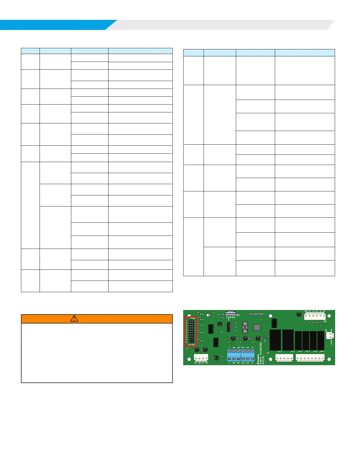
Figure 3: MT2310 I/O Expansion DIP Switches
TB1
H5
H6
H4
PWM
WSE
GND
HGR
GND
AUX1
GND
AUX2
GND
RV2
GND
COMP2
GND