oPTIonal Gas heaT
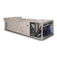
Daikin Applied Tubular Heater Series Package Heater Module
ANSI Z83.8-2013/CSA 2.6-2013
DANGER
FIRE OR EXPLOSION HAZARD
• Failure to follow safety warnings exactly could result in
serious injury, death or property damage.
• Be sure to read and understand the installation,
operation and service instructions in this manual.
• Improper installation, adjustment alteration, service
or maintenance can cause serious injury, death or
property damages.
• Do not store or use gasoline or other ammable vapors
and liquids in the vicinity of this or any other appliance.
• WHAT TO DO IF YOU SMELL GAS
— Do not try to light any appliance.
— Do not touch any electrical switch; do not use any
phone in your building.
— Leave the building immediately.
— Immediately call you gas supplier. Follow the gas
supplier’s instructions.
— If you cannot reach your gas supplier, call the re
department.
• Installation and service must be performed by a
qualied installer, service agency or the gas supplier.
DAT heater series modules are a recognized furnace
component is design certied by intertek testing services
(ETL) for outdoor installation and installation downstream from
refrigeration systems in cabinet applications.
This furnace must be installed in the designated non-
combustible heat chamber of the cabinet. If it is removed, it
is only to be replaced with an approved Original Manufacture
Equipment Supplier furnace(s), installed and operated as
specied by the approved Original Manufacture Equipment
Supplier. It is not designed to have any portion of the heat
exchanger outside the cabinet in which the furnace module is
housed.
The Rating Plate/Name Plate has been permanently attached
to the furnace assembly. It contains information including gas
type, maximum and minimum input rating, manifold pressure,
maximum and minimum inlet gas pressure, maximum and
minimum airow requirements, output capacity and electrical
rating for the furnace. The plate also includes model number,
serial number and scan code. This plate is to always remain
attached to the furnace.
This furnace must be applied in accordance with the
requirements of its listing.
Hooded and screened openings for combustion air have been
provided in the furnace(s) access door. The air opening provides
unrestricted combustion air to the burners and sized such that
a minimum free area is maintained. The minimum free area is
dened as 1 in2 (625mm2) per 4000 BTUH (2.345 kW).
The access door provides direct access to the furnace
vestibule where the burners, combustion inducer fan, ignition
controls and ignition safeties are housed.
The vent discharge is sized such that it is equal to or larger
than the discharge area of the combustion exhaust inducer fan.
A non-adjustable High Limit Switch will shut off the gas supply
to the main burners should the outlet air reach a temperature
exceed 250°F (121°C).
The cabinet supply air ow delivery package has been
designed to provide sufciently well distributed air ow across
the heat exchanger to limit temperature rise as follows:
• Aluminized Steel: 1030°F (575°C)
• 409 Stainless Steel: 1080°F (600°C)
Clearance from combustibles to be no less than as listed
below:
• Sides and back ..................... 6 in. (152 mm)
• Bottom ............................. 2 in. (51 mm)
• To p ............................... 6 in. (152 mm)
• Front............................. 36 in. (914 mm)
• Vent pipe to any combustible surface .... 6 in. (152 mm)
Do not use this package heater if any part has been under
water. Immediately call a qualied service technician to inspect
the heater and any gas control which has been under water.
IM 1058-8 • MAVERICK II ROOFTOP SYSTEMS 22 www.DaikinApplied.com
oPTIonal Gas heaT

 Loading...


