oPTIonal Gas heaT
Gas Furnace Design
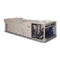
If the 8th digit in the model number is a “G”, the rooftop unit
was furnished with a factory installed furnace (Example,
MPS035FG). The Maverick commercial rooftop units are
available with either the low heat input or the high heat input
furnace (see capacities in Table 15). This packaged gas heat
rooftop unit is designed for outdoor non-residential installations
only.
The gas heat furnace design consists of a tubular heat
exchanger, in-shot burner manifold with gas valve, induced
combustion blower, gas heat DDC control module and all
operational safeties. The tubular heat exchanger can come
with the standard aluminized steel construction or the optional
stainless steel construction. The safety switches include a
high-limit temperature switch, an auxiliary high-limit switch,
a combustion blower proof of airow, and the ame roll-out
switch (see Figure 20).
The high limit switch is an automatic reset switch and it opens
up at 160°F to shut the furnace down and closes at 130°F. The
auxiliary limit switch is a manual reset and opens up at 180°F
to shut the furnace down.
Figure 19: Gas Heat Section
Gas Heating Capacity Data
Table 15: MPS 015F – 050F Gas Heating Capacities
Data
Unit Size
015–020 026–035 040–050
Low Heat High Heat Low Heat High Heat Low Heat High Heat
Heating Input (MBh) 240 480 300 600 400 800
Heating Output (MBh) 192 384 240 480 320 640
Steady State Efciency 80% 80% 80% 80% 80% 80%
Number of Stages 2 4 2 4 2 4
Turndown
1
4:1 8:1 4:1 8:1 4:1 8:1
Minimum Airow 2960 5920 3700 7400 4900 9800
Maximum Temperature Rise 60°F 100°F 60°F 85°F 60°F 85°F
Gas Main Pressure
Natural Gas (in. wc) 7-14 7-14 7-14 7-14 7-14 7-14
Liquid Propane (in. wc) 12-14 12-14 12-14 12-14 12-14 12-14
Manifold Pressure
Natural Gas (per gas valve)
Stage 1 (in. wc) 1.2 1.2 1.2 1.2 1.2 1.2
Stage 2 (in. wc) 3.2 3.2 3.2 3.2 3.2 3.2
Low re
2
0.4 0.4 0.4 0.4 0.4 0.4
Propane
Stage 1 (in. wc) 2.3 2.3 2.3 2.3 2.3 2.3
Stage 2 (in. wc) 10.0 10.0 10.0 10.0 10.0 10.0
Low re
2
N/A
Note:
1 Modulating gas heat only.
2 Modulating gas heat not available with propane.
Field Gas
Piping
oPTIonal Gas heaT
www.DaikinApplied.com 23 IM 1058-8 • MAVERICK II ROOFTOP SYSTEMS

 Loading...


