ESIE17-08 | Part 5. Appendix 5.3. Wiring diagram
R32 Sky-Air RZAG-M
15/11/18 | Version 1.1 Page 121
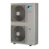
Figure 5-3: Wiring diagram - outdoor unit AZAS71MV1, RZASG71MV1
Notes
1. Refer to the wiring diagram sticker (on the back of the front plate) for how to use the BSI~BS3 and DS1 switches.
2. When operating, do not short-circuit protection device(s) S1PH, S1PL and Q1E.
3. Refer to the combination table and the option manual for how to connect the wiring to X6A and X77A.
4. Colours: BLK: Black, RED: Red, BLU: Blue, WHT: White, GRN: Green.
Legend
A1P Printed circuit board (main) R8 (A1P) Resistor
BS1~3 (A1P) Push-button switch S1PH High pressure switch
DS1 (A1P) Dipswitch S1PL Low pressure switch
E1~3 (A1P) Connector SEG1~3 (A1P) 7-segment display
F1U (A1P) Fuse T 31,5 A 250 V TC1 (A1P) Signal transceiver circuit
F2U (A1P) Fuse T 6,3 A 250 V U, V, W (A1P) Connector
F3U (A1P) Fuse T 6,3 A 250 V V1D (A1P) Diode
F6U (A1P) Fuse T 5 A 250 V V*R (A1P) Diode module
HAP (A1P) Light-emitting diode (service monitor is green) X*A (A1P) Connector
K1R (A1P) Magnetic relay (Y1S) X1M Terminal strip
K2R (A1P) Magnetic relay (Y2S) Y1E, Y3E Electronic expansion valve
K13R~K15R,
K10R (A1P)
Magnetic relay Y1~2S Solenoid valve (4-way valve)
K11M (A1P) Magnetic contactor Z*C Noise filter (Ferrite core)
L (A1P) Connector Z*F (A1P) Noise filter
M1C Compressor motor * Optional
M1F Fan motor # Field supply
N (A1P) Connector
PFC (A1P) Power factor correction
Symbols
PS (A1P) Switching power supply Connection
Q1DI Earth leakage circuit breaker (30mA) X1M Main terminal
Q1E Overload protection Earth wiring
R1T Thermistor (air) Field supply
R2T Thermistor (discharge) Option
R3T Thermistor (suction) Switch box
R4T Thermistor (heat exchanger) PCB
R5T Thermistor (heat exchanger middle) Wiring depending on model
R6T Thermistor (liquid) Protective earth
R7T Thermistor (fin) Field wire
AZAS71MV1, RZASG71MV1
OUTDOOR
Layout
INDOOR
Position of compressor terminal
SEE NOTE 3
Upper EEV
Lower EEV
SEE
NOTE 3
4D110098
 Loading...
