11 ■English
Indoor Unit Installation
9. Wiring
1. General instructions
• Make certain that all electric wiring work is carried out by qualied personnel according to the applicable legislation
and this installation manual, using a separate dedicated circuit.
Insufcient capacity of the power supply circuit or improper electrical construction may lead to electric shock or a re.
• Make sure to install a ground fault circuit interrupter.
Failure to do so may cause electric shock and a re.
• Do not turn on the power supply (branch switch, branch overcurrent circuit breaker) until all the works are nished.
• Multiple number of indoor units are connected to one outdoor unit. Name each indoor unit as A-unit, B-unit ….. and
the like. When these indoor units are wired to the outdoor unit, always wire the indoor unit to the terminal indicated
with the same symbol on the terminal block. If the wiring and the piping are connected to the different indoor units and
operated, it will result in malfunction.
• Make sure to ground the air conditioner.
Grounding resistance should be according to applicable legislation.
• Do not connect the ground wiring to gas or water pipings, lightning conductor or telephone ground wiring.
• Gas piping ........Ignition or explosion may occur if the gas leaks.
• Water piping ......Hard vinyl tubes are not effective grounds.
• Lightning conductor or telephone ground wiring ..... Electric potential may rise abnormally if struck by a lightning bolt.
• For electric wiring work, refer to also the “WIRING DIAGRAM” attached to the electrical wiring box cover.
• Carry out wiring between the outdoor units, indoor units and the remote controllers according to the wiring diagram.
• Carry out installation and wiring of the remote controller according to the “installation manual” attached to the remote
controller.
• Do not touch the Printed Circuit Board assembly. It may cause malfunction.
WARNING
• Do not use tapped wires, extension cords, or starburst connections, as they may cause overheating, electric shock, or re.
• Do not use locally purchased electrical parts inside the product. (Do not branch the power for the drain pump, etc., from the
terminal block.) Doing so may cause electric shock or re.
• Do not connect the power wire to the indoor unit. Doing so may cause electric shock or re.
CAUTION
• When clamping wiring, use the included clamping material to prevent outside pressure being exerted on the wiring
connections and clamp rmly. When doing the wiring, make sure the wiring is neat and does not cause the electrical wiring
box cover to stick up, then close the cover rmly.
• Outside the unit, separate the low voltage wiring (remote controller wiring) and high voltage wiring (wiring between units,
ground, and other power wiring) at least 2 in. so that they do not pass through the same place together. Proximity may cause
electrical interference, malfunctions, and breakage.
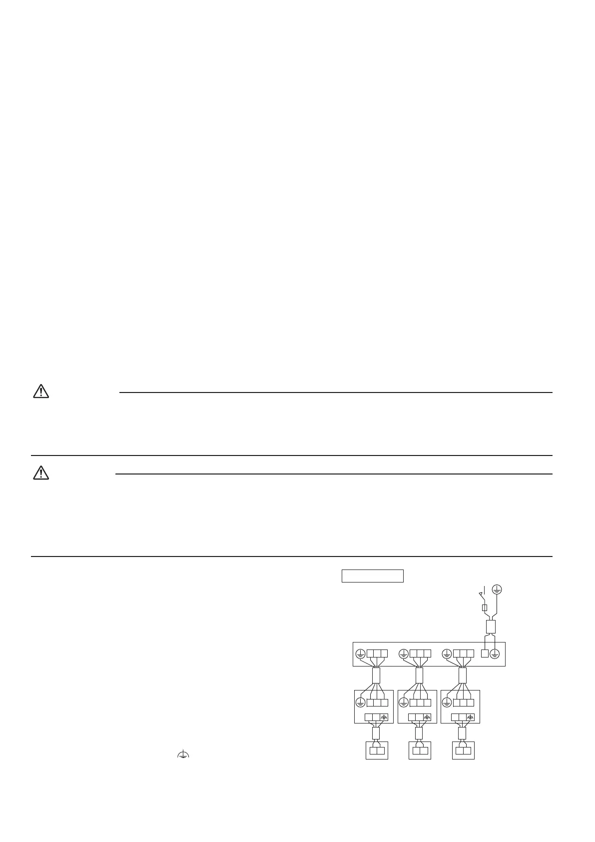
2. Wiring example
For the wiring of outdoor units, refer to the installation
manual attached to the outdoor units.
Conrm the system type.
• Multi system: 2 through 6 (The number of
connectable units will vary according to model) indoor
units connect to 1 outdoor unit. The indoor unit is
controlled by remote controller connected to each
indoor unit.
Multi system
Main switch
1 2 3
1 2 3
P P1 2
P P1 2
1 2 3
1 2 3
P P1 2
P P1 2
1 2 3
1 2 3
P P1 2
P P1 2
Fuse
Outdoor unit
Indoor
unit
Indoor
unit
Indoor
unit
Remote controller
NOTE
1. All transmission wiring except for the remote controller
wires is polarized and must match the terminal symbol.
2. In case a shielding wire is to be used, connect a
shielded portion with the
of a remote controller
terminal block.(Also, connect the ground for the remote
control to a grounded metal part.)
01_EN_3P674701-1B.indd 11 2022/06/02 10:06:25

 Loading...