MaInTenanCe
www.DaikinApplied.com 141 IM 893-10 • ROOFPAK SINGLEZONE UNITS
Field Wiring Terminals
All eld wiring terminals are spring clamp type, which offer
several advantages over traditional screw-type terminals:
• Spring connections do not require torquing
• Spring connections resist failure due to vibration
• Easily identiable terminal markers
• Combination spring release and square test ports Wire
connections require inserting (“1” in Figure 135 a stripped
wire a round port and clamping the stripped wire by
inserting a at-bladed screw driver in the adjacent square
port (“2” in Figure 135).
Figure 135: Terminal Connectors
Phase Voltage Monitor (PVM)
The phase voltage monitor (Figure 129)is designed to
protect three-phase loads from damaging power conditions.
A microprocessor-based voltage and phase sensing circuit
constantly monitors the three-phase voltages to detect harmful
power line conditions. When a harmful condition is detected,
its output relay is deactivated after a specied trip delay (Trip
Delay). The output relay reactivates after power line conditions
return to an acceptable level for a specied amount of time
(Restart Delay). The trip and restart delays prevent nuisance
tripping due to rapidly uctuating power line conditions.
There are two LEDs on the face of the PVM (“1” in Figure 129)
to indicate the following:
Table 36: LED Indication
Status LED Indicator
Normal operation, no faults, relay
energized
Green LED: steady ON
Loss of input phase (relay de-energized)
Red LED: ash twice, OFF, ash
twice, OFF, etc.
Voltage unbalance (relay de-energized)
Red LED: ash twice, OFF, ash
twice, OFF, etc.
High or low voltage (relay de-energized) Red LED: steady ON
Phase reversal (relay de-energized)
Red LED: pulse ON, OFF, ON,
OFF, etc.
Restart delay (fault cleared, PVM
pending restart, relay de-energized)
Green LED: pulse ON, OFF, ON,
OFF, etc.
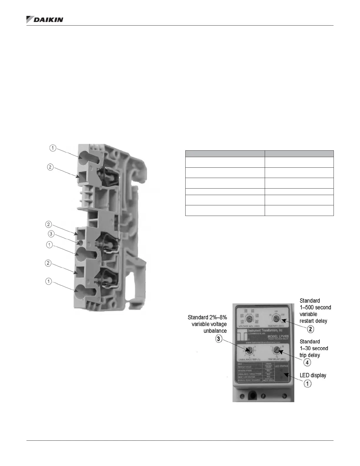
Other features:
• Standard 2% to 8% variable voltage unbalance (“3” in
Figure 136).
• Standard 1 to 500 second variable restart delay (“2” in
Figure 136).
• Standard 1 to 30 second trip delay (“4” in Figure
136) (except loss of phase, which trips at 1 second
nonadjustable).
Figure 136: Phase Voltage Monitor

 Loading...


