IM 893-10 • ROOFPAK SINGLEZONE UNITS 44 www.DaikinApplied.com
eleCTrICal InsTallaTIon
All Units
DANGER
Provide proper line voltage and phase balance. Improper line
voltage or excessive phase imbalance constitutes product
abuse. It can cause severe damage to the unit’s electrical
components.
The minimum circuit ampacity (wire sizing amps) is shown on
the unit nameplate. Refer to Table 17 for the recommended
number of power wires.
Copper wire is required for all conductors. Size wires in
accordance with the ampacity tables in Article 310 of the
National Electrical Code. If long wires are required, it may
be necessary to increase the wire size to prevent excessive
voltage drop. Wires should be sized for a maximum of 3%
voltage drop. Supply voltage must not vary by more than 10%
of nameplate. Phase voltage imbalance must not exceed 2%.
(Calculate the average voltage of the three legs. The leg with
voltage deviating the farthest from the average value must not
be more than 2% away.) Contact the local power company for
correction of improper voltage or phase imbalance.
A ground lug is provided in the control panel for each
disconnect or power block. Size grounding conductor in
accordance with Table 250-95 of the National Electrical Code.
In compliance with the National Electrical Code, an electrically
isolated 115V circuit is provided in the unit to supply the factory
mounted service receptacle outlet and optional unit lights.
This circuit is powered by a eld connected 15A, 115V power
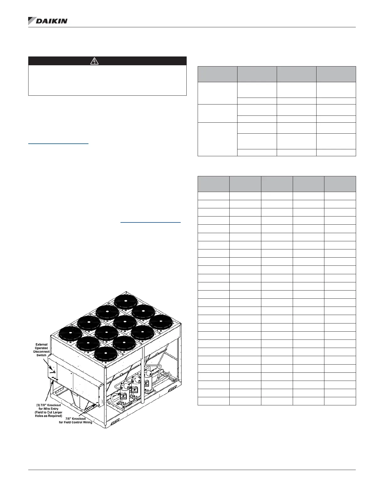
supply. Leads are brought into the RFS and RPS units through
a 7/8ʺ knockout in the bottom of the main control panel, near
the power wire entry point.
Figure 50: RCS 050D to 140D Power Wiring Connections
Table 16: Multiple Point Power Connection Options
Number of
electrical circuits
Disconnect
designation
Load
Location
(see Figure 9 on
page 9)
2
DS2
Supply and return
fan motors plus
controls
Main control panel
DS1 Balance of unit Main control panel
2
DS3 Electric heat
Electric heat
control panel
DS1 Balance of unit Main control panel
3
DS3 Electric heat
Electric heat
control panel
DS2
Supply and return
fan motors plus
controls
Main control panel
DS1 Balance of unit Main control panel
Table 17: RPS/RFS/RCS/RDT Recommended Power Wiring
Ampacity
Number of
Power Wires
per Phase
Number of
Conduits
Wire Gauge
Insulation
Rating (0°C)
30 1 1 10 60
40 1 1 8 60
55 1 1 6 60
70 1 1 4 60
85 1 1 3 60
95 1 1 2 60
130 1 1 1 75
150 1 1 1/0 75
175 1 1 2/0 75
200 1 1 3/0 75
230 1 1 4/0 75
255 1 1 250 75
285 1 1 300 75
310 1 1 350 75
335 1 1 400 75
380 1 1 500 75
400 2 2 3/0 75
460 2 2 4/0 75
510 2 2 250 75
570 2 2 300 75
620 2 2 350 75
670 2 2 400 75
760 2 2 500 75
765 3 3 250 75
855 3 3 300 75
930 3 3 350 75

 Loading...


