IM 893-10 • ROOFPAK SINGLEZONE UNITS 84 www.DaikinApplied.com
unIT oPTIons
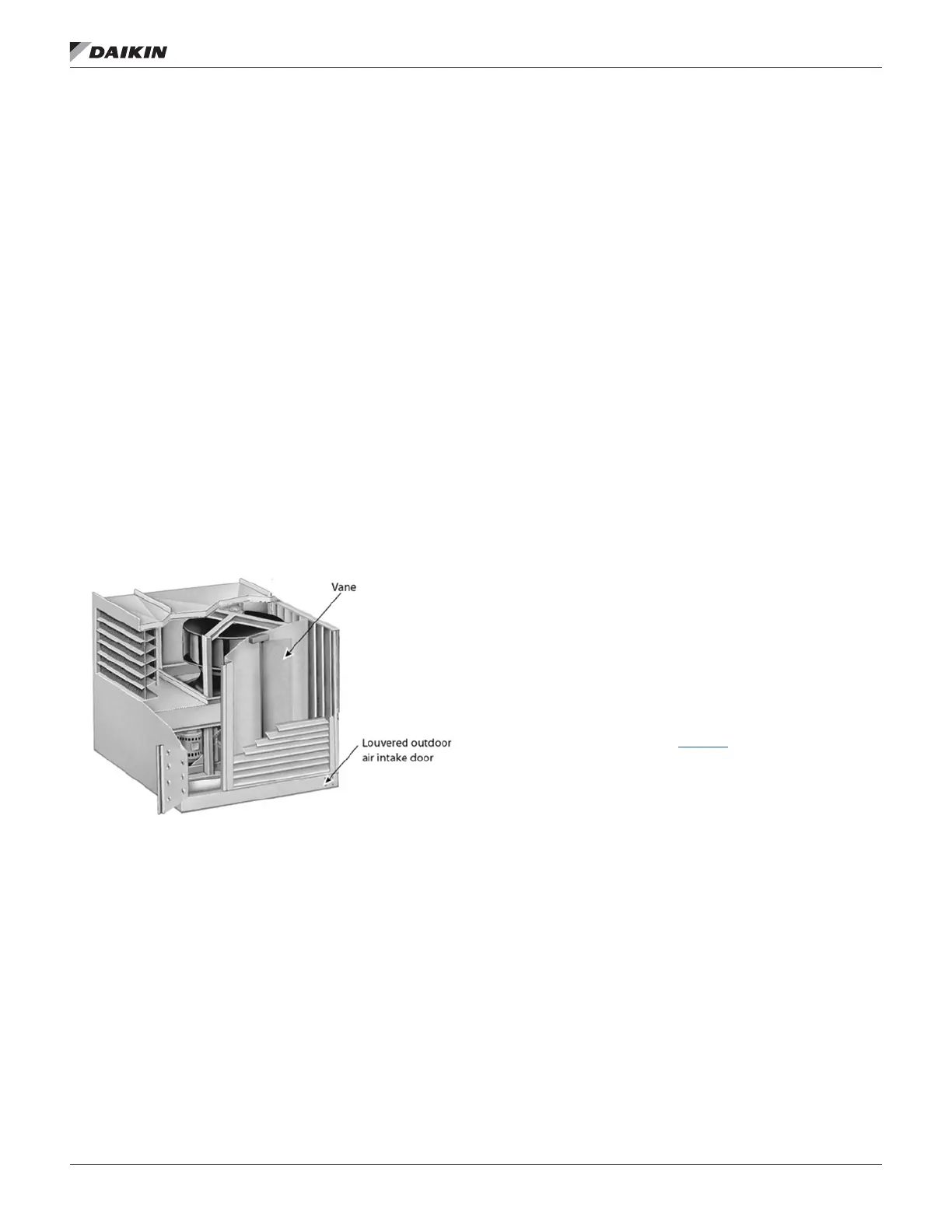
DesignFlow™ Outdoor Air Damper Option
DesignFlow™ airow measurement stations are located inside
the louvered outdoor air intake doors between the intake
louver and outside air dampers (Figure 84). Essentially, they
consist of a vane that is repositioned by airow, the amount of
rotation indicating the amount of airow. They are calibrated
precisely at the factory and no further calibration is required.
However, a leveling adjustment is required in the eld so that
the DesignFlow unit is in the same orientation as when it was
factory calibrated. See “DesignFlow Station Startup” below.
The rotational position of the DesignFlow unit vane is
translated into CFM by the microprocessor in the MicroTech
III control system. The position of the vane is determined by
two things—the force of the airow impacting the vane and
the gravitational effect on the vane. Gravity is the only factor
at the lower CFM end of the range. On a correctly leveled unit,
this gravitational effect will be the same as when the unit was
calibrated in the factory.
Accurately leveling a station involves applying a precise
mechanical force against the vane. This force should cause
the vane to move to a specic position if the DesignFlow unit is
correctly leveled.
Figure 84: DesignFlow Station
DesignFlow Station Startup
Before initial startup of the rooftop unit, carry out the following
procedure on both the right-hand (control panel side) and
left-hand (side opposite the control panel) DesignFlow station
vanes (see Figure 84).
1. Verify that power is supplied to the unit’s MicroTech III
control system. The DesignFlow startup procedure cannot
be completed without use of the MicroTech III controls.
2. Unlock and open the louvered outdoor air intake door on
the side of the unit (see Figure 84).
3. The swinging vane on the measurement station is locked
in place for shipment. Unlock it by removing the two
shipping screws. One is located one inch from the top of
the vane and the other one inch from the bottom of the
vane. Both are about eight inches in from the outer edge
of the vane.
4. Examine the station for shipping damage. Manually rotate
the vane and verify that it does not rub against anything.
5. Manually hold the vane closed against the mechanical
stop at the top of the assembly. Then, read the current
vane leveling position on the MicroTech III keypad/display.
Do this by viewing the LH Lvl Pos= or RH Lvl Pos=
parameter in the Min OA setup menu. The LH Lvl Pos=
parameter indicates the current position of the vane
for the left-hand DesignFlow station (side opposite the
control panel). The RH Lvl Pos= parameter indicates
the current position of the vane for the right-hand
DesignFlow station (control panel side).
Important: Wait several seconds until the value on the
keypad stabilizes before taking the reading. For detailed
information regarding operation and navigation through
the unit keypad, refer to OM 920.
6. Conrm the value of the reading. Ideally, it should read
close to 20.00 (19.50 to 20.50 is acceptable). If the
reading is out of range, loosen the screws xing the
mechanical stop at the top of the assembly, make a
small adjustment, and recheck until the reading is in the
specied range.
NOTE: Generally, adjustments should not be necessary.
7. Locate the leveling component kit, which is shipped with
the unit, in the unit main control panel.
8. Duct tape the fulcrum alignment plate to the bottom
corner of the vane (see Figure 85) aligning it as follows:
a. The bottom edge of its notches should be ush
with the bottom edge of the vane.
b. The side of one notch should be even with the
bend near the outer edge of the vane.
c. The plate should be at against the outer surface
of the vane.

 Loading...


