PreParIng unIT for oPeraTIon
www.DaikinApplied.com 47 IM 893-10 • ROOFPAK SINGLEZONE UNITS
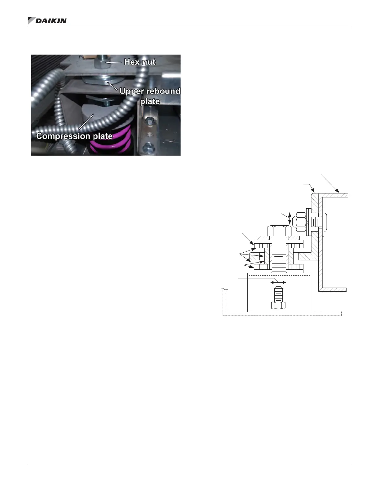
Figure 56: Spring Mount
Relief Damper Tie-Down
Economizer sections with a 30ʺ or 40ʺ return fan have a relief
damper that is tied down for shipping. Remove the two brackets
and two screws before operation to allow free movement of
dampers. Access is from inside the economizer section.
Adjustment of Seismic Restraints
Spring mounted supply air and return air fans may be ordered
with factory installed seismic restraints. Refer to Figure 56. The
system consists of four snubbers, one located next to each
spring isolator. These snubbers will allow free movement of
the fan assemblies during normal operation because normal
operation will not cause fan movements that exceed 0.25ʺ (6
mm). However, they will restrain the fan assembly and limit
movement to 0.25ʺ (6 mm) in any direction if an abnormal
condition were to occur.
The position the fan will assume during normal operation will
be determined by actual job site airow and static pressure.
Therefore, for proper operation, the seismic restraints must be
eld adjusted as part of the normal Check, Test, and Start on
page 102 procedure. When the fan is operating in a normal
manner there should be no contact between the snubber
restrainer angle and the snubber neoprene bumper. However,
in a “seismic event,” the snubber will limit movement of the
spring mounted fan assembly to 0.25ʺ (6 mm) in any direction,
thereby helping to prevent the fan from being tossed about and
damaged, or causing damage.
When a seismic restraint is properly adjusted and the fan
is operating normally, the neoprene center bumper will be
centered within the 2ʺ (51 mm) diameter hole in the restrainer
angle, and the restrainer angle will be centered vertically
between the anges of the neoprene center bumper. This
results in 0.25ʺ (6 mm) clearance in all directions. When the
fan is turned off the restrainer angle may come to rest on the
neoprene center bumper.
The seismic restraint is adjustable in all directions. Vertical
slots in the restrainer angle and horizontal slots in the blower
base allow the restrainer angle to be adjusted up and down
and back and forth. The neoprene center bumper is mounted
on a slotted hole allowing its adjustment in and out.
Removing the neoprene center bumper bolt allows removal,
disassembly, and replacement of the neoprene components.
Figure 57: Cross Section of Seismic Restraint
Fan base channel
Adjust up or down
or back and forth
Snubber neoprene
bumper
Snubber neoprene
bumper
.25 (6 mm) gap
(fan running)
Adjust in and out
Snubber restrainer angle

 Loading...


