WIrIng dIagraMs
www.DaikinApplied.com 51 IM 893-10 • ROOFPAK SINGLEZONE UNITS
WIrIng dIagraMs
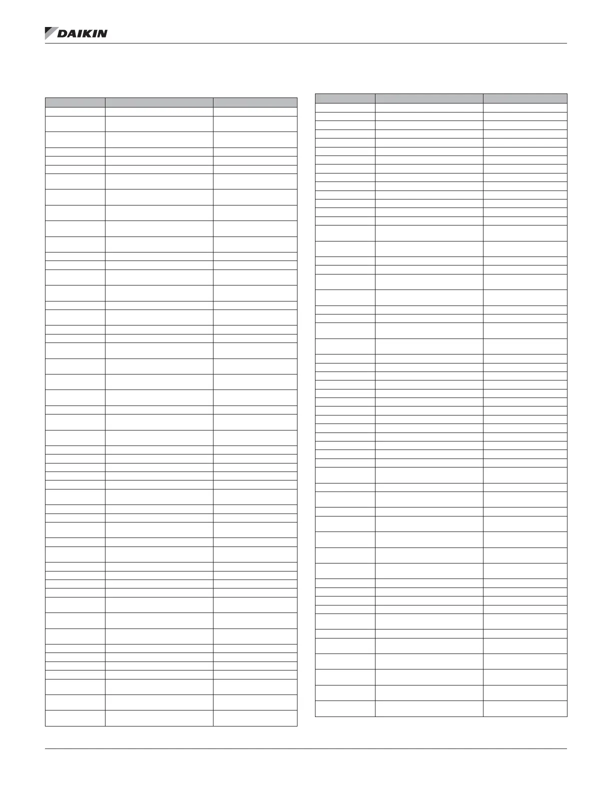
Legend
ID Description Standard location
ACT3, 4 Actuator motor, economizer Economizer section
ACT5
Actuator motor, discharge
isolation damper
Discharge section
ACT6
Actuator motor, return air
isolation damper
Return section
ACT7 Actuator motor, heat face/bypass Coil section, heat
ACT8 Actuator motor, cool face/bypass Coil section, cool
ACT10, 11 Actuator motor, exhaust dampers Return section
ACT12
Actuator motor, enthalpy wheel
bypass damper
Energy recovery section
AFD10
Adjustable frequency drive,
supply fan
AFD/supply fan section
AFD11
Adjustable frequency drive,
evap cond fans
Main/RCE control box
AFD20
Adjustable frequency drive,
return/exhaust fan
AFD/ret. ex. fan section
AFD60
Adjust freq drive,
energy recovery wheel(s)
Energy recovery section
AS Airow switch, burner blower Gas heat box
BM Burner blower motor Heat section, gas
C1–8
Power factor capacitors,
compressors
Condenser section
C10
Power factor capacitors,
supply fan
Supply Fan section
C11 Capacitors, Speedtrol, circuit #1 Condenser bulkhead
C20
Power factor capacitors,
return fan
Return section
C21 Capacitors, Speedtrol, circuit #2 Condenser bulkhead
CB10 Circuit breaker, supply fan Main control box
CB11
Circuit breaker, evaporative
condenser fan(s)
Main/Cond control box
CB20
Circuit breaker,
return/exhaust fan
Main control box
CB60
Circuit breaker,
energy recovery wheel
Main control box
CCB1, 2
Compressor control boards,
refrig circuits
Main control box
CDS2 Discharge thermostat VFD compressor
CPC
Circuit board, main,
micro controller
Main control box
CPR
Circuit board, expansion,
micro controller
Main control box
CS1, 2 Control switches, refrig circuits Main/Cond control box
DAT Discharge air temperature sensor Discharge section
DFLH Design ow left hand sensor Return section
DFRH Design ow right hand sensor Return section
DHL Duct hi-limit Main control box
DS1
Disconnect, total unit or
cond/heat
Main control box
DS2 Disconnect, SAF/RAF/controls Main control box
DS3 Disconnect, electric heat Electric heat box
DS4
Disconnect, condenser
(RCS Only)
RCS control box
EAT Exhaust air temperature sensor Energy recovery section
EFT
Entering fan air
temperature sensor
Supply fan section
EHB1 Staged electric heat board Main control box
ERB1 Energy recovery board Main control box
ERM1 Energy recovery wheel motor #1 Energy recovery section
ERM2 Energy recovery wheel motor #2 Energy recovery section
F1A, B
Fuse, control circuit transformer
(T1), primary
Main control box
F1C
Fuse, control circuit transformer
(T1), secondary
Main control box
F2
Fuse, control circuit transformer
(T2), primary
Main control box
F3 Fuse, burner blower motor Main control box
F2M Fuses, VFD compressor Main control box
FB11, 21 Fuseblock, Speedtrol Main/Cond control box
FB2M Fuseblock, VFD compressor Main control panel
FB31–40
Fuseblock, electric heat
(top bank)
Electric heat box
FB41–50
Fuseblock, electric heat
(bottom bank)
Electric heat box
FB65
Fuseblock, evap cond
sump heater
Main/Cond control box
ID Description Standard location
FD Flame detector Heat section, gas
FLC Fan limit control Heat section, gas
FP1, 2 Frost protection, refrig circuits Coil section, cool
FS1, 2 Freezestat control Coil section, heat/cool
FSG Flame safeguard Gas heat box
GFR1, 2 Ground fault relay Main control box
GFS1, 2 Ground fault sensor Main control box
GFR4 Ground fault relay, condenser Condenser control box
GFS4 Ground fault sensor, condenser Condenser control box
GRD Ground All control boxes
GV1 Gas valve, pilot Heat section, gas
GV2 Gas valve, main/safety Heat section, gas
GV3 Gas valve, redundant/safety Heat section, gas
GV4–8 Gas valve, main, hi turn down Heat section, gas
HL1–10
Hi-limits, pwr, elec heaters
(top bank)
Heat section, electric
HL11–20
Hi-limits, pwr, elec heaters
(bottom bank)
Heat section, electric
HL22 Hi-limits, gas heat (pre-lters) Supply fan section
HL23 Hi-limits, gas heat (nal lters) Final lter section
HL31–40
Hi-limits, ctl elec heaters
(top bank)
Heat section, electric
HL41–50
Hi-limits, ctl elec heaters (bottom
bank)
Heat section, electric
HP1–4 Hi-pressure controls, refrig Main control box
HP5 Hi-pressure controls, gas Heat section, gas
HS1
Heat switch, electric heat
shutdown
Main control box
HS3
Heat switch, electric heat
deadfront interlock
Electric heat box
HTR1–6 Crankcase heaters On compressors
HUM1 Humidstat sensor Energy recovery section
IT Ignition transformer Gas heat box
LAT Leaving air temperature sensor Energy recovery section
LP1, 2 Low-pressure controls, refrig Main control box
LP5 Low-pressure control, gas Heat section, gas
LR10 Line Reactor, supply fan Inverter bypass box
LR20 Line reactor, return/exhaust fan Inv. bypass/main cntl box
LR2M Line reactor, VFD compressor Condensing section
LS1, 2 Limit switch, low re, high re Gas heat box
LT10–23 Light, cabinet sections Supply fan section
M1–8 Contactor, compressor Main/Cond control box
M10 Contactor, supply fan Main control box
M11–18
Contactor, condenser fans,
circuit #1
Main/Cond control box
M20 Contactor, return fan Main control box
M21–28
Contactor, Condenser fans,
circuit #2
Main/Cond control box
M29 Contactor, burner motor Gas heat box
M30
Contactor, reversing, inverter
bypass, supply fan
Inverter bypass box
M31–39
Contactor, electric heat
(top bank)
Electric heat box
M40
Contactor, reversing, Inverter
Bypass, Return Fan
Inverter bypass box
M41–50
Contactor, electric heat
(bottom bank)
Electric heat box
M60 Contactor, energy recovery wheel Main control box
M64 Contactor, sump pump Main/Cond control box
M65 Contactor, sump heater Main/Cond control box
MCB Microprocessor circuit board Main control box
MF3, MF4
Cooling fan, VFD compressor
panel
VFD compressor panel
MJ Mechanical Jumper All control boxes
MMP1–8
Manual motor protector,
compressors
Main/Cond control box
MMP10
Manual motor protector,
supply fan
Main control box
MMP11–18
Manual motor protector,
cond fans, ckt#1
Main/Cond control box
MMP20
Manual motor protector,
return fan
Main control box
MMP21–28
Manual motor protector,
cond fans, ckt#2
Main/Cond control box

 Loading...


