IM 1287-6 • REBEL APPLIED ROOFTOP 36 www.DaikinApplied.com
Lifting Equipment
Lifting equipment is supplied by the user or their designate.
This is typically selected around the unit certied information
of the equipment to be lifted and the available lifting equipment
planned to be at the site where the lift is to take place. It is the
responsibility of the Lifting Director to follow a standard practice
of lift planning and equipment selection, like that found in the
ASME P30 series of standards. Lifting plan and equipment
must ensure that the only contact with the unit is at that lifting
brackets. Straps, chains or spreader bars that are likely to be
used shall not come in contact with the unit.
CAUTION
Lifting mechanisms must not make contact with the unit beyond the lifting
bracket. Extreme care must be used when rigging the unit to prevent
damage to the control panels, unit handles, unit piping, and unit frame.
Lifting Points
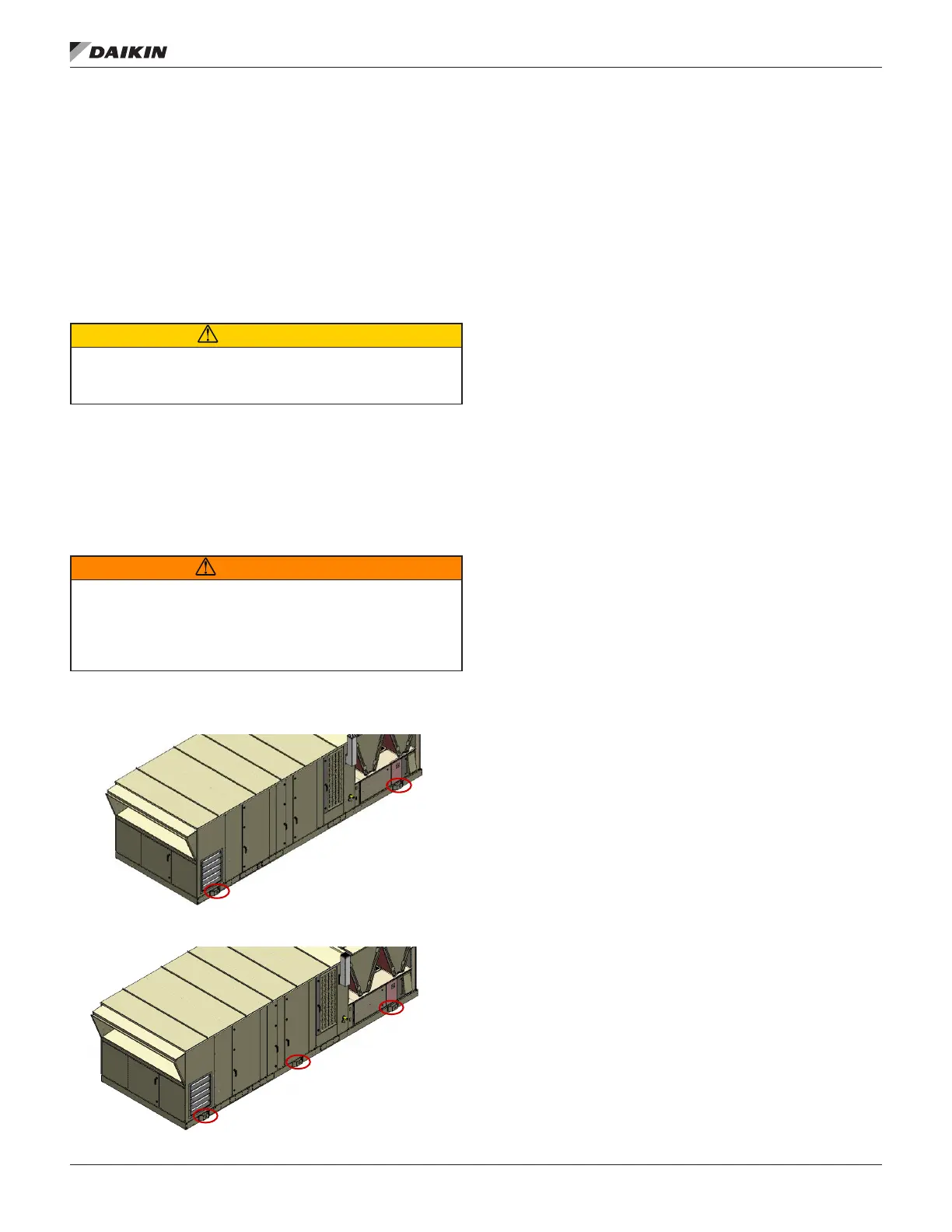
Lifting points are predetermined by design. When lifting,
all factory installed lifting brackets must be used. Figure 53
illustrates typical 4 point and 6 point lifting congurations. Unit
must remain level throughout the entire lifting event. Level is
dened as one end being no more than 0.25” per foot of unit
length to the opposite end.
WARNING
Be aware that the center of gravity may not necessarily be in the geometric
center of the unit. No additional items can be added to a lift with the unit as
it may affect the center of gravity and cause unit damage, property damage,
severe personal injury, or death. Refer to as-designed, certied drawings for
weight, center of gravity location and details specic to unit conguration.
Figure 53: Typical Lifting Points Locations
4 Lifting Points
6 Lifting Points
Transit and Temporary Storage
If the unit is stored for an intermediate period before installation
or moved to a dierent location, take these additional
precautions:
1. Support the unit well along the length of the base rail.
2. Level the unit (no twists or uneven ground surface).
3. Provide proper drainage around the unit to prevent
ooding of the equipment.
4. Provide adequate protection from vandalism, mechanical
contact, etc.
5. Securely close the doors and lock the handles.
6. If there are isolation dampers, make sure they are
properly installed and fully closed to prevent the entry
of animals and debris through the supply and return air
openings.
7. Cover the supply and return air openings on units without
isolation dampers.
8. Long term storage in humid environments may cause
condensate corrosion on steel surfaces. Consider adding
a desiccant material to alleviate corrosion concerns.
When the unit is being tied down for transit, the maximum
allowable attachment angle from the vertical is 30 degrees in
the opposite direction of lifting in Figure 52. Shimming of the
unit under the lifting brackets or tie-down points must be used
to ensure even contact along the length of the base rail.


 To Next Page
 Loading...