www.DaikinApplied.com 41 IM 1287-6 • REBEL APPLIED ROOFTOP
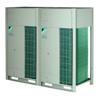
17. Connect the wires per the wiring schematic. In the low
voltage raceway, connect the plugs that mate. The wires
should be routed up to the platform and wire-tied such
that the plugs sit on the platform. High voltage wires that
are pulled back from the landing should be routed around
the low voltage trough and passed into the high voltage
raceway on the other side. Pull to the appropriate landing
spot and connect the wires. High voltage wires that are
split should be routed to the appropriate power block
on the opposite side of the split. If there is pneumatic
tubing for pressure switches or transducers that cross
the shipping split, the tubing will need to be routed in the
low voltage raceway. Connect matching labels with the
provided barbed hose tting.
Figure 73: Route Wires
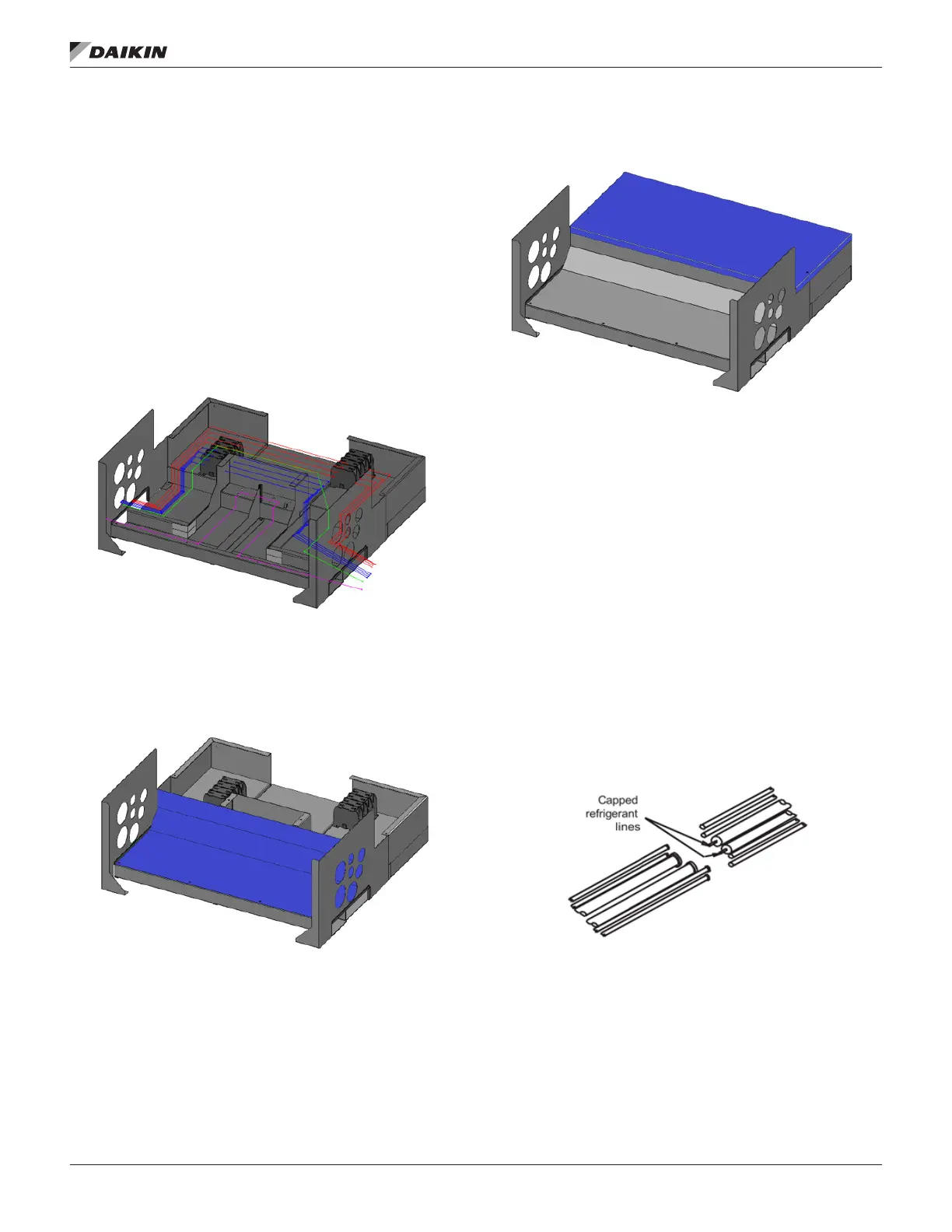
18. After all the wires have been properly connected, attach
the low voltage cover (Figure 74) with the plastic clips
through the holes on the front edge.
Figure 74: Low Voltage Cover
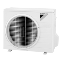
19. Attach the high voltage cover (Figure 75).
Figure 75: High Voltage Cover
20. Make refrigeration connections.
IMPORTANT:
If the indoor coil is within 18” of the Shipping Split, remove
Expansion Valve Bulbs before brazing the suction lines
to prevent heat damage to the bulb. These will need to
be reattached once all the brazing is completed to have a
properly functioning machine. Install the sensing bulbs in the
same location as received.
Refrigeration tubes are shipped with a nitrogen holding
charge. This should be safely released through the
depression of a Schrader valve until the charge has been
reduced to atmospheric pressure.
Removed the caps of the refrigeration tubing preferably
by using a tube cutter. If a tube cutter is not possible, take
caution to not have any remaining copper chips inside of
the tube before brazing starts. Reconnect refrigerant piping.
Figure 76 illustrates what the installer sees at the shipping
split.
Figure 76: Braze Refrigerant Pipe Joints
 Loading...