IM 1287-6 • REBEL APPLIED ROOFTOP 40 www.DaikinApplied.com
12. Install raceway junction box and connect the wiring.
DANGER
LOCKOUT/TAGOUT all power sources prior to wiring or servicing the unit.
Hazardous voltage can cause serious injury or death. Disconnect electric
power before servicing equipment. More than one disconnect may be
required to de-energize the unit.
CAUTION
Connect the power block correctly and maintain proper phasing. Improper
installation can cause severe equipment damage.
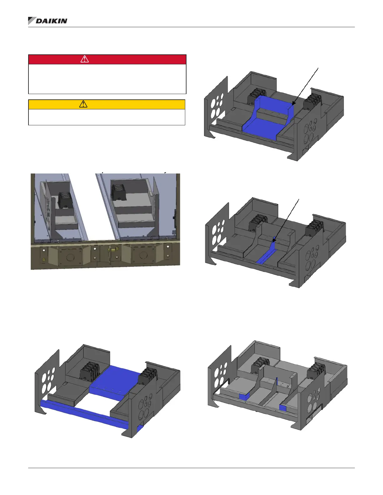
The wiring to the unit will be pulled back into either side of
the shipping split modules. This wiring needs to be routed per
the wiring diagram to ensure the proper operation of the unit
(Figure 68).
Figure 68: Terminal Box Prior to Assembly
13. Install the low voltage raceway (Figure 69) by pealing
back the plate and fastening in place by aligning the
center hole with the hole in the deck, and the connection
of the high voltage box by fastening the two screws in
the back.
Figure 69: Low Voltage Raceway
14. Install the high-to-low voltage divider (Figure 70).
Figure 70: High-to-Low Voltage Divider
15. Install the low voltage divider (Figure 71).
Figure 71: Low Voltage Divider
16. Install the edge protector on the low voltage divider and
install the UHMW tape on the corners of the low voltage
raceway (2 - 4” pieces stacked vertical on each corner).
Figure 72: Edge Protectors
 Loading...