IM 1287-6 • REBEL APPLIED ROOFTOP 66 www.DaikinApplied.com
Field Control Wiring
DANGER
LOCKOUT/TAGOUT all power sources prior to wiring or servicing the unit.
Electrical shock hazard that may cause severe injury or death. Connect only
low voltage NEC Class II circuits to the terminal blocks. Reinstall and secure
all protective front panels when the wiring installation is complete.
Rebel Applied units are available with several control schemes
which may require low voltage eld wiring. Use the Unit
Specic Electrical Schematics to determine which control
connections will be required for installation. Check unit specic
electrical documentation in the door of the control panel. Figure
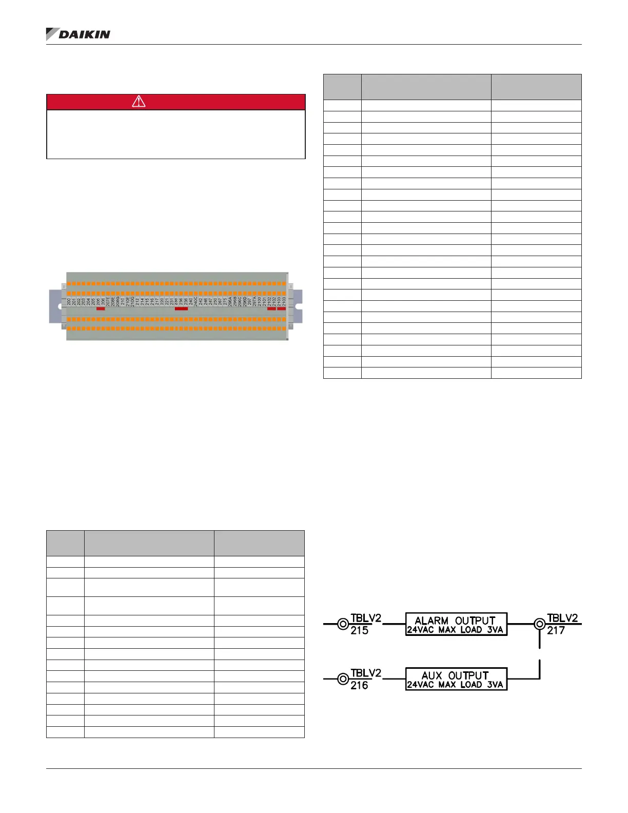
136 is a graphical representation of TB2 and Table 11 shows
the possible eld connections that can be made.
Figure 136: Graphical Representation of TB2
Rebel Applied units operate with 115V and 24V control circuit
power. All eld control wiring connections are made at the class
II terminal block TBLV2 which is located in the Low Voltage
Control Panel, shown in Figure 139.
NOTE: The installation of all eld wiring, must comply with all
applicable local codes and ordinances. The warranty
may be limited or certain aspects excluded if the eld
wiring is not in accordance with these standards.
If a single conduit containing 24V and 115V wiring is
run above the rooine between units, consider the
24V wiring within as an NEC Class I wiring system.
Table 11: Potential eld Connections and Locations on
TB2
Terminal
Block
Number
Description Signal
200 Power 24VAC
201 Signal for Tennant Override Contact Closure
202
Condensate Overow Switch Contact
1
Contact Closure
203
Condensate Overow Switch Contact
2 & feed into SD2 E-stop series
Contact Closure
204 Feed from SD2 into E-Stop Series Contact Closure
205 Field Provisions for E-Stop Contact Closure
206 Field Provisions for E-Stop Contact Closure
207E Relative Humidity Sensor #1 (ZRH1) 4-20mA
208E Humidity Sensor 4-20mA
208G Relative Humidity Sensor #2 (ZRH2) 4-20mA
210 Space Temperature Sensor 1 Class II Thermistor
210E Space Temperature Sensor 2 Class II Thermistor
210G Space Temperature Sensor 3 Class II Thermistor
212 Setpoint Adjustment, Wallstat 0-5 VDC Signal
214 CO2 / Ext OA Reset 0-10V DC
Terminal
Block
Number
Description Signal
215 Alarm Output 24VAC relay
216 Alarm Return 24VAC relay
217 Fan Operation 24VAC relay
220 Freezestat Sensor Terminal 1 Contact Closure
221 Freezestat Sensor Terminal 2 Contact Closure
231 Alarm Reset Contact Closure
236 Controller Common
240 Local / Remote Status Relay output
240C System Ready Output Relay output
242 Cooling system Interlock (From Field) Contact Closure
246 Reheat Valve Cmd 0-10V DC
247 Cooling Capacity Input 0-10V DC
250 Cooling Actual Capacity Output 0-10V DC
267 SAF1 Capacity Cmd (From Field) 0-10V DC
275 EF Capacity Cmd (From Field) 0-10V DC
296A Return Air SD Aux Contact Relay output
296B Return Air SD Aux Contact Relay output
296C Supply Air SD Aux Contact Relay output
296D Supply Air SD Aux Contact Relay output
297 Passive Ventilation Input Contact Closure
297A Passive Ventilation Input Contact Closure
2100 Smoke Purge - Purge Contact Closure
2101 Smoke Purge - Pressurize Contact Closure
2102 Smoke Purge - Vent Contact Closure
2103 Smoke Purge - Shutdown Contact Closure
Field Output Signals
There are several output signals on the MicroTech Controller
that may be available for eld connections. For example, the
Alarm Output and the Auxiliary Output, shown in Figure 137,
can be used to send signals to external systems.
A eld supplied 24VAC relay must be installed in order to
interface these outputs with a system external to the unit.
When the respective signal is active, the signal terminal
will be energized with 24VAC. The coil of the eld supplied
24VAC relay must be wired between the signal terminal and
the common terminal. These would be terminals TBLV2-215
and TBLV2-217 in the case of the Alarm Output and terminals
TBLV2-216 and TBLV2-217 in the case of the Auxiliary Output.
The eld installed relay coil may draw no more than 3VA or
125mA at 24VAC.
Figure 137: Field Output Schematic


 To Next Page
 Loading...