www.DaikinApplied.com 73 IM 1287-6 • REBEL APPLIED ROOFTOP
Follow the below general installation rules in order to avoid
any condensation accumulation which can cause severe water
accumulation in the duct or a humidier malfunction.
NOTICE
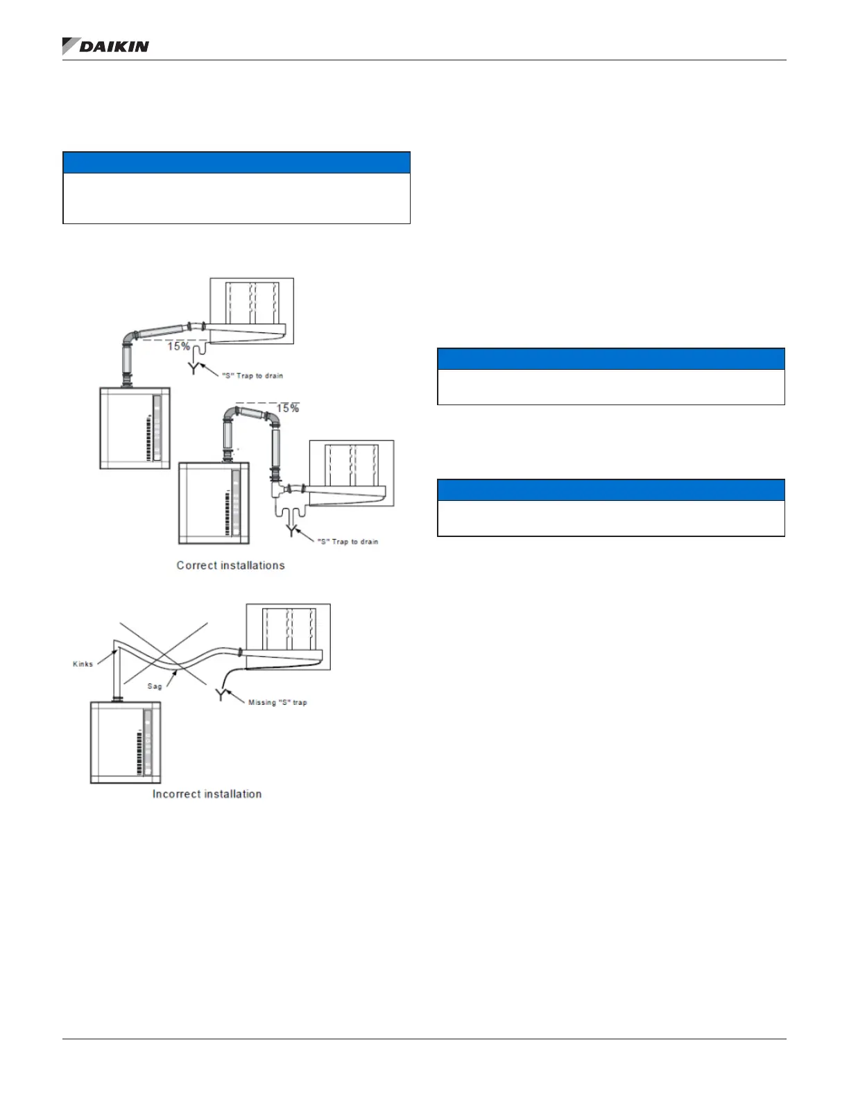
Risk of malfunction. Avoid kinks, sags and areas where condensate
can become trapped. Plumbing installation should conform to Local and
National Codes.
Figure 145: Proper and Improper Installation Examples
1. The slope of the steam hose (rigid or exible) should
not be less than 15% (7 horizontal lengths for 1 vertical
length) in order to ensure continuous drainage of
condensation back to humidier or to steam trap.
2. The lowest point of any steam hose or rigid pipe must be
the humidier. If necessary, a steam trap (S Type) should
be installed higher than the static pressure of the system
by at least 2 inches (51mm).
3. Total length of the steam hose or rigid pipe should not
exceed 15 feet (5 meters). Longer runs will result in
added condensation losses. Whenever possible, use
insulated copper piping. Flexible steam hose should
be used for short runs (up to 15 feet or 5m) or for
interconnecting between the rigid pipe runs. For longer
runs, please consult the factory.
4. Whenever using rigid copper pipe, use insulation to
diminish condensation build up.
Single steam outlet
• Run one steam line from the steam outlet of the
evaporation chamber of the humidier to the Multi-Steam
header (a reducer is welded at the inlet of the Multi-
Steam header).
• Use steam hose and clamps to make the connection from
hard insulated copper pipe to the Multi-Steam and the
humidier.
NOTICE
Never reduce the diameter of the steam lines. Improper size will over-
pressurize the humidier.
Condensate drain outlet
The Multi-Steam has a 1/2” (15mm) or 3/4” (20mm) NPT (or
BSPT) condensate drain connection.
NOTICE
Remove the 1/2” (15mm) or 3/4” (20mm) cap (shipping
protection) from the condensate drain before the installation.
• Run a pipe (same size as the condensate drain
connection) as directly as possible from the condensate
drain outlet to the oor drain with a proper slope and
install a steam trap to prevent any steam leakage from
the drain.
• The steam trap (S Type) should be installed higher than
the static pressure of the system by at least 2 inches
(51mm).
Start-up procedure
Follow this start-up procedure to avoid improper system
operation:
1. Ensure that plumbing connections have been done in
accordance with the instructions in this manual.
1. Verify that the steam supply line is connected properly to
the Multi-Steam.
2. Verify that the Humidier Grid is properly pitched.
3. Verify that the Humidier Grid condensate drain is
connected to the drain line.
Maintenance
• Inspect the Multi-Steam at start-up and during normal
operation.
• Make sure all hose connections are secure and there are
no leaks in the line.
 Loading...