IM 1287-6 • REBEL APPLIED ROOFTOP 82 www.DaikinApplied.com
b. Set the operating schedule as required using
keypad menus. Main Menu\ViewStatus\Date/ Time
and Date/Time/Schedules.
NOTE: When used with a Building Automation System, these
settings may need to be kept at the default of no
schedule:
Maintaining Control Parameter Records
Daikin Applied recommends that the MicroTech controller’s
setpoints and parameters be recorded and saved for future
reference. If the Microprocessor Control Board (MCB) requires
replacement, this record facilitates entering the unit’s proper
data. The following tables display all the setpoints, monitoring
points, and program variables oered by MicroTech plus the
keypad road map used to nd each parameter.
A number of menus and menu items that appear on the unit
keypad/display are conditional and may not apply to a specic
unit, depending on the unit software conguration. The unit
software conguration is dened by a “Software Conguration
Code” shown on a label located near the keypad/display. The
Software Conguration Code also can be displayed via the
six menu items in the Cong Code menu on the unit keypad/
display.
NOTE: Keep a record of any changes made to any of these
items.
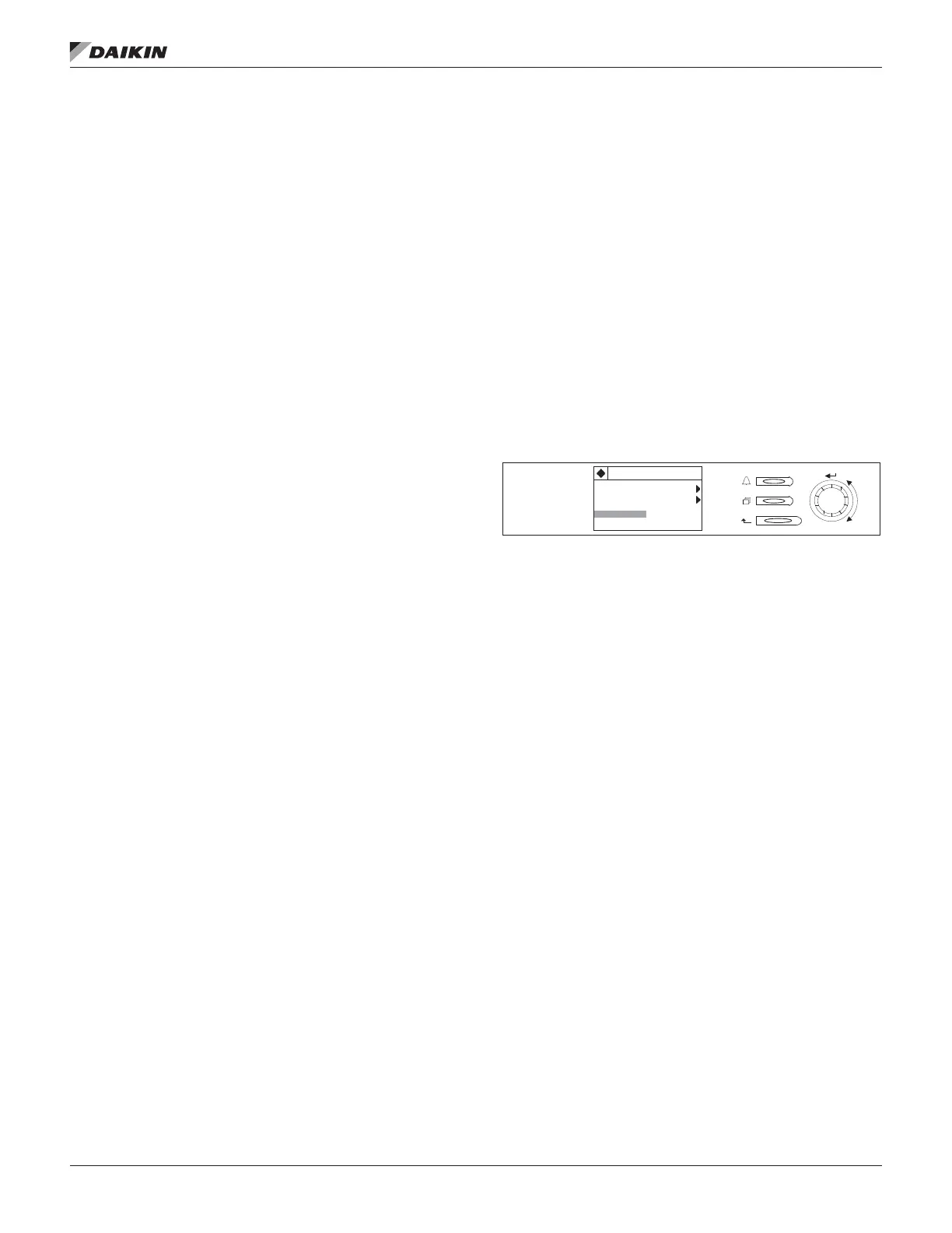
Using the Keypad/Display
The keypad/display consists of a 5-line by 22 character display,
three keys and a “push and roll” navigation wheel. There is an
Alarm Button, Menu (Home) Button, and a Back Button. The
wheel is used to navigate between lines on a screen (page)
and to increase and decrease changeable values when editing.
Pushing the wheel acts as an Enter Button.
The rst line on each page includes the page title and the line
number to which the cursor is currently “pointing”. The line
numbers are X/Y to indicate line number X of a total of Y lines
for that page. The left most position of the title line includes an
“up” arrow to indicate there are pages “above” the currently
displayed items, a “down” arrow to indicate there are pages
“below” the currently displayed items or an “up/down” arrow
to indicate there are pages “above and below” the currently
displayed page.
Each line on a page can contain status only information or
include changeable data elds. When a line contains status
only information and the cursor is on that line all but the value
eld of that line is highlighted meaning the text is white with
a black box around it. When the line contains a changeable
value and the cursor is at that line, the entire line is highlighted.
Each line on a page may also be dened as a “jump” line,
meaning pushing the navigation wheel will cause a “jump” to
a new page. An arrow is displayed to the far right of the line to
indicate it is a “jump” line and the entire line is highlighted when
the cursor is on that line.
The keypad/display Information is organized into ve main
menus or menus groups; Alarm Lists Menu, System Summary
Menu, Standard Menus, Extended Menus and Advanced
Menus.
NOTE: Only menus and items that are applicable to the
specic unit conguration are displayed.
Figure 151: Keypad Controls
The Alarm Lists Menu includes active alarm and alarm log
information. The System Summary Menu includes status
information indicating the current operating condition of the
unit. Standard Menus include basic menus and items required
to setup the unit for general operation. These include such
things are control mode, occupancy mode and heating and
cooling setpoints. Extended Menus include more advanced
items for “tuning” unit operation such as PI loop parameters
and time delays. Advanced Menus include the most advanced
items such as “unit conguration” parameters and service
related parameters. These generally do not need changing
or accessing unless there is a fundamental change to or a
problem with the unit operation.
Passwords
When the keypad/display is rst accessed, the Home Key
is pressed, the Back Key is pressed multiple times, or if the
keypad/display has been idle for the Password Timeout timer
(default 10 minutes), the display will show a “main” page where
the user can enter a password or continue without entering a
password.
Various menu functions are accessible or inaccessible,
depending on the access level of the user, and the password
they enter, if any. There are four access levels, including no
password, Level 2, Level 4, and Level 6, with Level 2 having
the highest level of access. Without entering a password, the
user has access only to basic status menu items. Entering
the Level 6 password (5321) allows access to the Alarm Lists
Menu, Quick Menu, and the View Status Unit Menus group.
Entering the Level 4 password (2526) allows similar access
as Level 6 with the addition of the Commission Unit Menu,
Manual Control, and Service Menu groups. Entering the Level
2 password (6363) allows similar access as Level 4 with
System Summary
3/23
Advanced Menus
Alarm Lists
Unit State= Cooling
25%
 Loading...