5 Preparation
Installer and user reference guide
13
RXYSQ4~6T8V/YB
VRV IV-S system air conditioner
4P482277-1 – 2017.04
5.3.3 To select the piping size
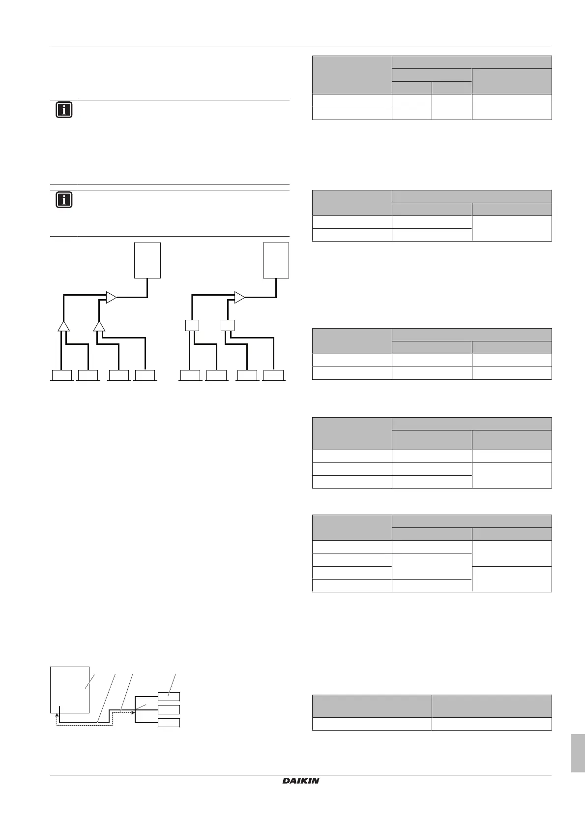
Determine the proper size referring to following tables and reference
figure (only for indication).
INFORMATION
▪ Combination of VRVDX and RADX indoor units is not
allowed.
▪ Combination of RA DX and AHU indoor units is not
allowed.
▪ Combination of RADX and aircurtain indoor units is not
allowed.
INFORMATION
If you install RA DX indoor units, you have to configure
field setting [2‑38] (= type of installed indoor units). See
"7.2.8Mode 2: Field settings"on page31.
A
B-1 B-2
C-1 C-2 C-3 C-4 E E E E
1 1
3-1 3-2 3-3 3-4
A
D
RA DXVRV DX
D
4
4
5 5 5 5
2 2
2 2
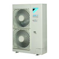
1 Outdoor unit
2 Refrigerant branch kits
3-1~3-4 VRVDX indoor units
4 BP units
5 RADX indoor units
A Piping between outdoor unit and (first) refrigerant branch
kit
B-1 B-2 Piping between refrigerant branch kits
C-1~C-4 Piping between refrigerant branch kit and indoor unit
D Piping between refrigerant branch kit and BP unit
E Piping between BP unit and RADX indoor unit
In case the required pipe sizes (inch sizes) are not available, it is
also allowed to use other diameters (mm sizes), taken the following
into account:
▪ Select the pipe size nearest to the required size.
▪ Use the suitable adapters for the change-over from inch to mm
pipes (field supply).
▪ The additional refrigerant calculation has to be adjusted as
mentioned in "6.7.3 To determine the additional refrigerant
amount"on page23.
A: Piping between outdoor unit and (first)
refrigerant branch kit
When the equivalent pipe length between outdoor and indoor units is
90m or more, the size of the main gas pipe must be increased (size-
up). If the recommended gas pipe (size-up) is not available, you
must use the standard size (which might result in a small capacity
decrease).
a Outdoor unit
b Main gas pipe
c Increase
d First refrigerant branch kit
e Indoor unit
Outdoor unit
capacity type (HP)
Piping outer diameter size (mm)
Gas pipe Liquid pipe
Standard Size-up
4+5 15.9 19.1 9.5
6 19.1 22.2
B: Piping between refrigerant branch kits
Choose from the following table in accordance with the indoor unit
total capacity type, connected downstream. Do not let the
connection piping exceed the refrigerant piping size chosen by the
general system model name.
Indoor unit capacity
index
Piping outer diameter size (mm)
Gas pipe Liquid pipe
<150 15.9 9.5
150≤x≤182 19.1
Example: Downstream capacity for B-1 = capacity index of unit 3-1
+ capacity index of unit 3-2
C: Piping between refrigerant branch kit and
indoor unit
Use the same diameters as the connections (liquid, gas) on the
indoor units. The diameters of the indoor units are as follows:
Indoor unit capacity
index
Piping outer diameter size (mm)
Gas pipe Liquid pipe
15~50 12.7 6.4
63~140 15.9 9.5
D: Piping between refrigerant branch kit and BP
unit
Total capacity index
of connected indoor
units
Piping outer diameter size (mm)
Gas pipe Liquid pipe
15~62 12.7 6.4
63~149 15.9 9.5
150~182 19.1
E: Piping between BP unit and RA DX indoor unit
Indoor unit capacity
index
Piping outer diameter size (mm)
Gas pipe Liquid pipe
15~42 9.5 6.4
50 12.7
60 9.5
71 15.9
5.3.4 To select refrigerant branch kits
For piping example, refer to "5.3.3 To select the piping size" on
page13.
Refnet joint at first branch (counting from outdoor unit)
When using refnet joints at the first branch counted from the outdoor
unit side, choose from the following table in accordance with the
capacity of the outdoor unit. Example: Refnet joint A→B‑1.
Outdoor unit capacity type
(HP)
Refrigerant branch kit
4~6 KHRQ22M20T



 To Next Page