6 Installation
Installer and user reference guide
26
RXYSQ4~6T8V/YB
VRV IV-S system air conditioner
4P482277-1 – 2017.04
WARNING
▪ After finishing the electrical work, confirm that each
electrical component and terminal inside the electrical
components box is connected securely.
▪ Make sure all covers are closed before starting up the
unit.
NOTICE
Do not operate the unit until the refrigerant piping is
complete. Running the unit before the piping is ready will
break the compressor.
NOTICE
If the power supply has a missing or wrong N-phase,
equipment will break down.
NOTICE
Do NOT install a phase advancing capacitor, because this
unit is equipped with an inverter. A phase advancing
capacitor will reduce performance and may cause
accidents.
NOTICE
Never remove a thermistor, sensor, etc., when connecting
power wiring and transmission wiring. (If operated without
thermistor, sensor, etc., the compressor may break down.)
NOTICE
▪ The reversed phase protection detector of this product
only functions when the product starts up.
Consequently reversed phase detection is not
performed during normal operation of the product.
▪ The reversed phase protection detector is designed to
stop the product in the event of an abnormality when
the product is started up.
▪ Replace 2 of the 3 phases (L1, L2, and L3) during
reverse-phase protection abnormality.
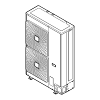
6.8.3 Guidelines when knocking out knockout
holes
NOTICE
Precautions when making knockout holes:
▪ Avoid damaging the casing.
▪ After making the knockout holes, we recommend you
remove the burrs and paint the edges and areas
around the edges using repair paint to prevent rusting.
▪ When passing electrical wiring through the knockout
holes, wrap the wiring with protective tape to prevent
damage.
a Knockout hole
b Burr
c Sealant etc.
6.8.4 Guidelines when connecting the electrical
wiring
Keep the following in mind:
▪ If stranded conductor wires are being used, install a round crimp-
style terminal on the tip. Place the round crimp-style terminal on
the wire up to the covered part and fasten the terminal with the
appropriate tool.
a Stranded conductor wire
b Round crimp-style terminal
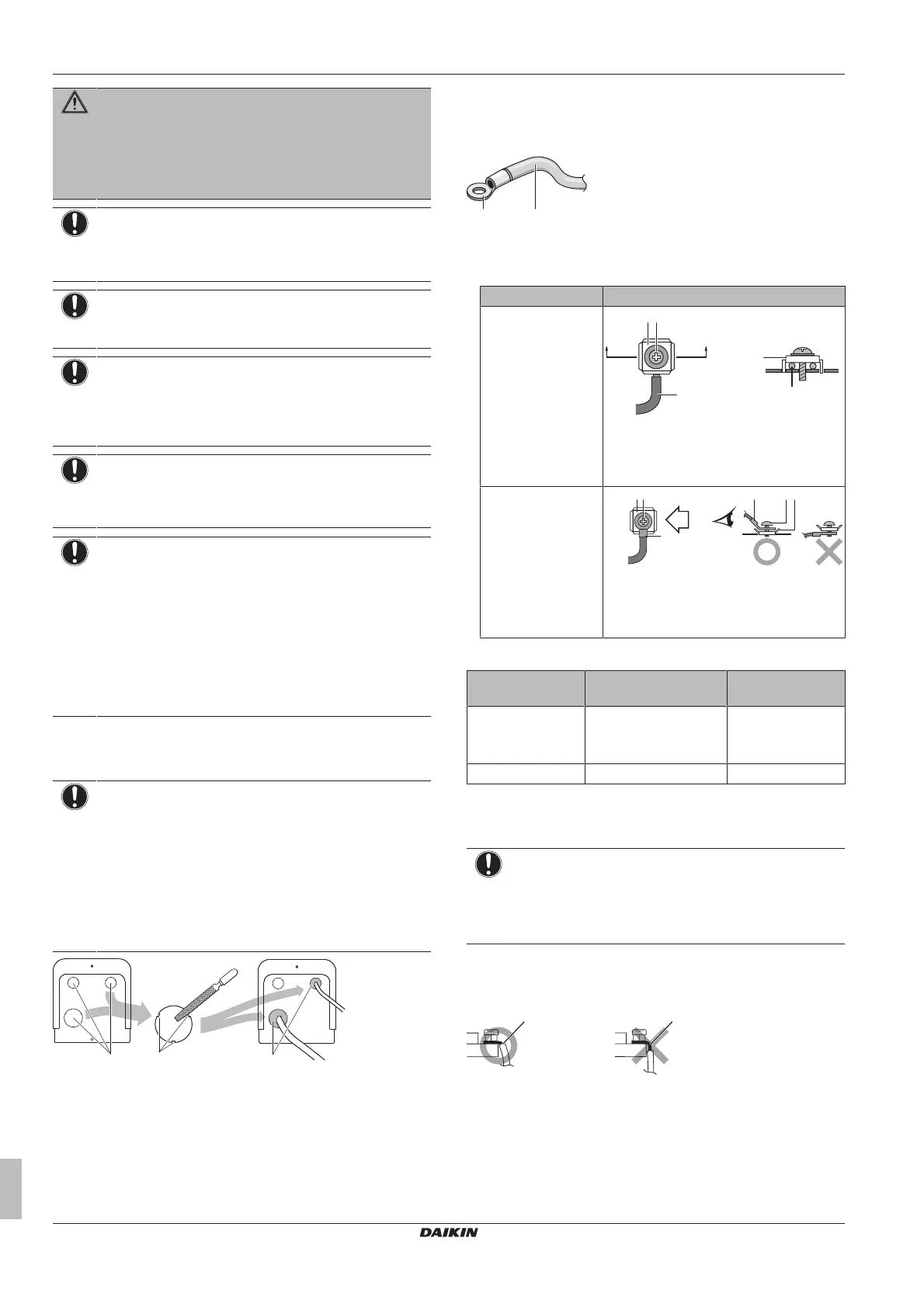
▪ Use the following methods for installing wires:
Wire type Installation method
Single core wire
a Curled single core wire
b Screw
c Flat washer
Stranded conductor
wire with round
crimp-style terminal
a Terminal
b Screw
c Flat washer
Tightening torques
Wiring Screw size Tightening torque
(N•m)
Power supply wiring
(power supply +
shielded ground)
M5 2.2~2.7
Transmission wiring M3.5 0.8~0.97
6.8.5 To connect the electrical wiring on the
outdoor unit
NOTICE
▪ Follow the wiring diagram (delivered with the unit,
located at the inside of the service cover).
▪ Make sure the electrical wiring does NOT obstruct
proper reattachment of the service cover.
1 Remove the service cover. See "6.2.2 To open the outdoor
unit"on page16.
2 Strip insulation (20mm) from the wires.
a Strip wire end to this point
b Excessive strip length may cause electrical shock or
leakage.
3 Connect the transmission wiring as follows:
 Loading...