5 Preparation
Installer and user reference guide
9
RXYSQ4~6T8V/YB
VRV IV-S system air conditioner
4P482277-1 – 2017.04
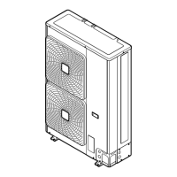
a VRV IV-S Heat pump outdoor unit
b Refrigerant piping
c VRV direct expansion (DX) indoor unit
d User interface (dedicated depending on indoor unit type)
e BP box (required to connect Residential Air (RA) or Sky Air
(SA) direct expansion (DX) indoor units)
f Residential Air (RA) direct expansion (DX) indoor units
g User interface (wireless, dedicated depending on indoor
unit type)
4.5 Combining units and options
4.5.1 About combining units and options
NOTICE
To be sure your system setup (outdoor unit+indoor unit(s))
will work, you have to consult the latest technical
engineering data for VRV IV-S heat pump.
The VRV IV-S heat pump system can be combined with several
types of indoor units and is intended for R410A use only.
For an overview which units are available you can consult the
product catalogue for VRV IV-S.
An overview is given indicating the allowed combinations of indoor
units and outdoor units. Not all combinations are allowed. They are
subject to rules (combination between outdoor-indoor, combinations
between indoor units, etc.) mentioned in the technical engineering
data.
4.5.2 Possible combinations of indoor units
In general following type of indoor units can be connected to a VRV
IV-S heat pump system. The list is non-exhaustive and is depending
on both outdoor unit model and indoor unit model combinations.
▪ VRV direct expansion (DX) indoor units (air to air applications).
▪ SA/RA (Sky Air/Residential Air) direct expansion (DX) indoor units
(air to air applications). Further referred to as RADX indoor units.
These indoor units require a BP box.
▪ AHU (air to air applications): EKEXV-kit+EKEQ-box are required,
depending on application.
▪ Aircurtain (air to air applications): CYV/CAV (Biddle) series,
depending on application.
INFORMATION
▪ Combination of VRVDX and RADX indoor units is not
allowed.
▪ Combination of RA DX and AHU indoor units is not
allowed.
▪ Combination of RADX and aircurtain indoor units is not
allowed.
4.5.3 Possible options for the outdoor unit
INFORMATION
Refer to the technical engineering data for the latest option
names.
Refrigerant branching kit
Description Model name
Refnet header KHRQ22M29H
Refnet joint KHRQ22M20T
For the selection of the optimal branching kit, please refer to
"5.3.4To select refrigerant branch kits"on page13.
Cool/heat selector
In order to control the cooling or heating operation from a central
location, the following option can be connected:
Description RXYSQ4~6_V RXYSQ4~6_Y
Cool/heat selector
switch
KRC19-26A KRC19-26A
Cool/heat selector
PCB
EBRP2B —
Cool/heat selector
cable
— EKCHSC
With optional fixing
box for the switch
KJB111A KJB111A
External control adaptor (DTA104A61/62)
To instruct specific operation with an external input coming from a
central control the external control adaptor can be used. Instructions
(group or individual) can be instructed for low noise operation and
power consumption limitation operation.
The external control adapter has to be installed in the indoor unit.
PC configurator cable (EKPCCAB)
You can make several commissioning field settings through a
personal computer interface. For this option EKPCCAB is required
which is a dedicated cable to communicate with the outdoor unit.
The user interface software is available on http://
www.daikineurope.com/support-and-manuals/software-downloads/.
5 Preparation
5.1 Overview: Preparation
This chapter describes what you have to do and know before going
on-site.
It contains information about:
▪ Preparing the installation site
▪ Preparing the refrigerant piping
▪ Preparing the electrical wiring
5.2 Preparing installation site
Do NOT install the unit in places often used as work place. In case
of construction works (e.g. grinding works) where a lot of dust is
created, the unit must be covered.
Choose the installation location with sufficient place for carrying the
unit in and out of the site.