13 Technical data
Installer and user reference guide
41
RXYSQ4~6T8V/YB
VRV IV-S system air conditioner
4P482277-1 – 2017.04
13 Technical data
A subset of the latest technical data is available on the regional Daikin website (publicly accessible). The full set of latest technical data is
available on the Daikin extranet (authentication required).
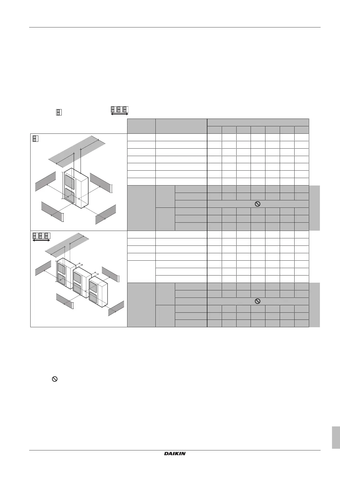
13.1 Service space: Outdoor unit
When mounting units side by side, the piping route must be to the front, to the back or downwards. In this case the piping route to the side is
not possible.
When mounting the units side by side and routing the piping to the back, you must keep a distance of ≥250mm between the units (instead of
≥100mm as shown on the figures below).
Single unit (
) | Single row of units ( )
1+2
1
A~E
a b c d e e
B
e
D
H
B
H
D
H
U
(mm)
a
b
c
d
e
e
B
e
D
A
B
C
D
E
H
B
H
U
H
D
B — ≥100
A, B, C — ≥100 ≥100 ≥100
B, E — ≥100 ≥1000 ≤500
A, B, C, E — ≥150 ≥150 ≥150 ≥1000 ≤500
D — ≥500
D, E — ≥1000 ≥1000 ≤500
B, D — ≥100 ≥500
B, D, E H
B
<H
D
H
B
≤½H
U
≥250 ≥750 ≥1000 ≤500
½H
U
<H
B
≤H
U
≥250 ≥1000 ≥1000 ≤500
H
B
>H
U
H
B
>H
D
H
D
≤½H
U
≥100 ≥1000 ≥1000 ≤500
½H
U
<H
D
≤H
U
≥200 ≥1000 ≥1000 ≤500
H
D
>H
U
≥200 ≥1700 ≥1000 ≤500
H
U
a
b
≥100
≥100
c
d
e
e
B
e
D
A
B
C
D
E
H
B
H
D
A, B, C — ≥200 ≥300 ≥1000
A, B, C, E — ≥200 ≥300 ≥1000 ≥1000 ≤500
D — ≥1000
D, E — ≥1000 ≥1000 ≤500
B, D H
D
>H
U
≥300 ≥1000
H
D
≤½H
U
≥250 ≥1500
½H
U
<H
D
≤H
U
≥300 ≥1500
B, D, E H
B
<H
D
H
B
≤½H
U
≥300 ≥1000 ≥1000 ≤500
½H
U
<H
B
≤H
U
≥300 ≥1250 ≥1000 ≤500
H
B
>H
U
H
B
>H
D
H
D
≤½H
U
≥250 ≥1500 ≥1000 ≤500
½H
U
<H
D
≤H
U
≥300 ≥1500 ≥1000 ≤500
H
D
>H
U
≥300 ≥2200 ≥1000 ≤500
A,B,C,D Obstacles (walls/baffle plates)
E Obstacle (roof)
a,b,c,d,e Minimum service space between the unit and obstacles A, B, C, D and E
e
B
Maximum distance between the unit and the edge of obstacle E, in the direction of obstacle B
e
D
Maximum distance between the unit and the edge of obstacle E, in the direction of obstacle D
H
U
Height of the unit
H
B
,H
D
Height of obstacles B and D
1 Seal the bottom of the installation frame to prevent discharged air from flowing back to the suction side through the bottom of the unit.
2 Maximum two units can be installed.
Not allowed
 Loading...