13 Technical data
Installer and user reference guide
43
RXYSQ4~6T8V/YB
VRV IV-S system air conditioner
4P482277-1 – 2017.04
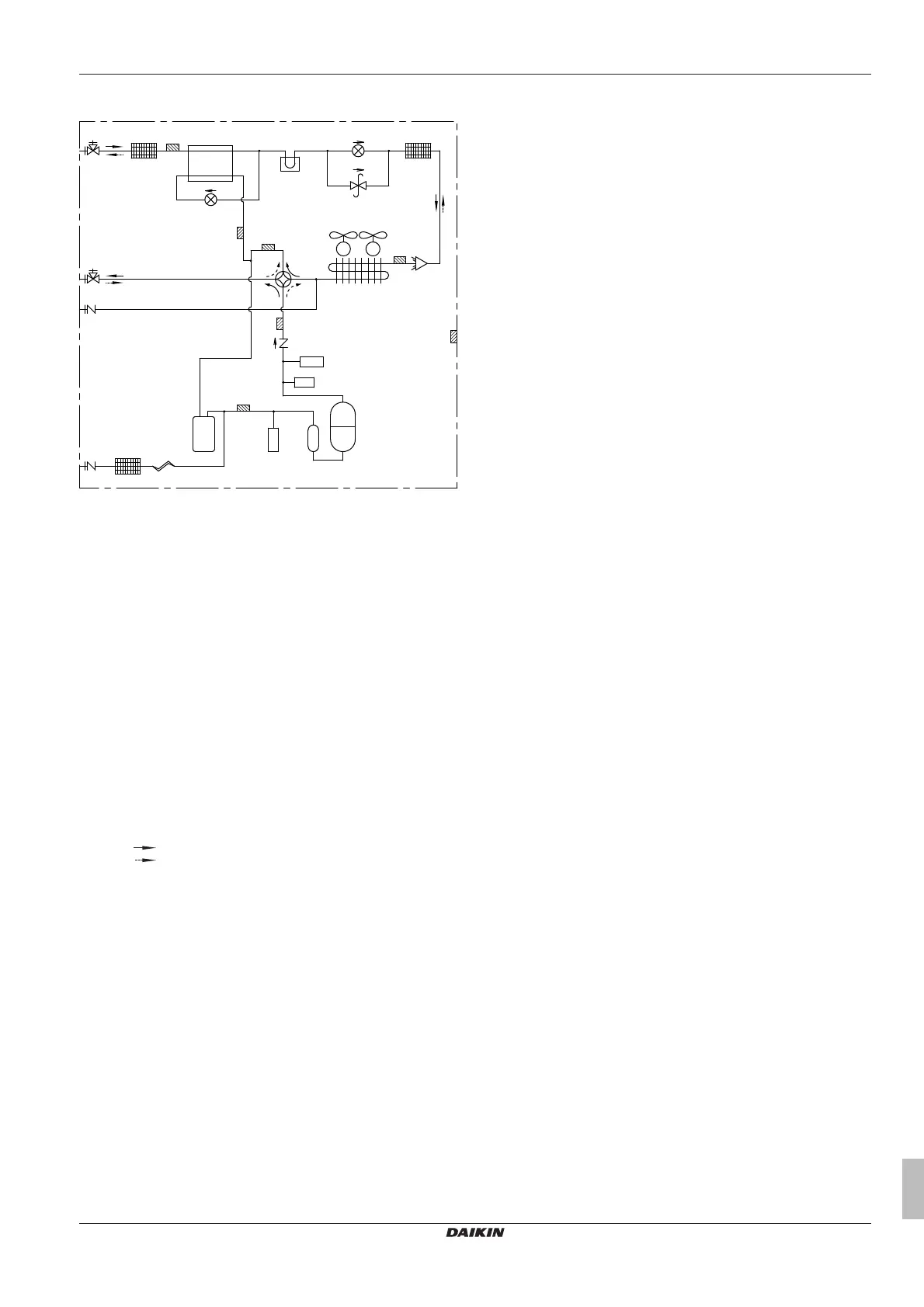
13.2 Piping diagram: Outdoor unit
R7T
Y1E
R3T
R4T
R5T
R2T
S1NPL
S1PH
M1C
INV
S1NPH
Y1S
Y3E
R6T
R1T
b
a
g
h
k c
j
l
i
c d
m
c
e
f
M1F M2F
a Stop valve (gas)
b Stop valve (liquid)
c Filter (3×)
d Subcool heat exchanger
e Pressure regulating valve
f Heat exchanger
g Service port (high pressure)
h Check valve
i Compressor accumulator
j Capillary tube
k Service port (refrigerant charge)
l Accumulator
m Heat sink PCB (only for RXYSQ4~6_V)
M1C Compressor
M1F-M2F Fan motor
R1T Thermistor (air)
R2T Thermistor (discharge)
R3T Thermistor (suction 1)
R4T Thermistor (heat exchanger)
R5T Thermistor (suction 2)
R6T Thermistor (subcool heat exchanger)
R7T Thermistor (liquid pipe)
S1NPH High pressure sensor
S1NPL Low pressure sensor
S1PH High pressure switch
Y1E Electronic expansion valve (main)
Y3E Electronic expansion valve (subcool heat exchanger)
Y1S Solenoid valve (4‑way valve)
Heating
Cooling
 Loading...