Installation
Installation manual
14
RZAG71~140N7V1+Y1
Sky Air Alpha-series
4P573382-1 – 2019.04
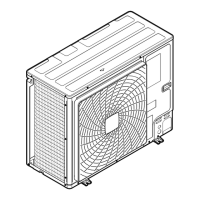
c
a
d
e
1~ 50 Hz
220-240 V
3N~ 50 Hz
380-415 V
V1 Y1
L1 L2 L3
L1 L2 L3
N
b
b
a
a
a
I, II, III, IV Pair, twin, triple, double twin
M, S Master, slave
a Interconnection cables
b Power supply cable
c Earth leakage circuit breaker
d Fuse
e User interface
INFORMATION
Some indoor units may need a separate power supply in
order to guarantee maximum capacity. See the installation
manual of the indoor unit.
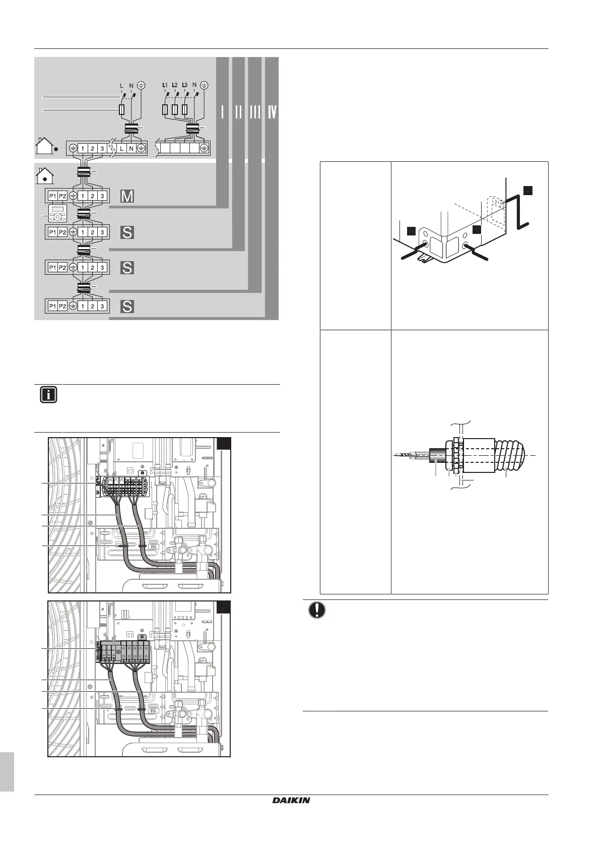
a Interconnection cable
b Power supply cable
c Earth
d Cable tie
3 Fix the cables (power supply and interconnection cable) with a
cable tie to the stop valve attachment plate and route the wiring
according to the illustration above.
4 Choose a knockout hole and remove the knockout hole by
tapping on the attachment points with a flat head screwdriver
and a hammer.
5 Route the wiring through the frame and connect the wiring to
the frame at the knockout hole.
Routing through
the frame
Choose one of the 3 possibilities:
a Power supply cable
Note: Route the interconnection cable
together with the refrigerant piping. See
"4.6.1To finish the outdoor unit
installation"on page15.
Connecting to the
frame
When cables are routed from the unit, a
protection sleeve for the conduits (PG
insertions) can be inserted at the knockout
hole.
When you do not use a wire conduit,
protect the wires with vinyl tubes to
prevent the edge of the knockout hole from
cutting the wires.
A Inside of the outdoor unit
B Outside of the outdoor unit
a Wire
b Bush
c Nut
d Frame
e Hose
NOTICE
Precautions when making knockout holes:
▪ Avoid damaging the casing and underlying piping.
▪ After making the knockout holes, we recommend to
remove the burrs and paint the edges and areas
around the edges using repair paint to prevent rusting.
▪ When passing electrical wiring through the knockout
holes, wrap the wiring with protective tape to prevent
damage.
6 Reattach the service cover.
7 Connect an earth leakage circuit breaker and fuse to the power
supply line.
 Loading...