Technical data
Installation manual
18
RZAG71~140N7V1+Y1
Sky Air Alpha-series
4P573382-1 – 2019.04
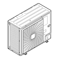
7.2 Piping diagram: Outdoor unit
Service port (with 5/16" flare)
Stop valve
Filter
PCB cooling
Muffler
Electronic expansion valve
4‑way valve
High pressure switch
Low pressure switch
Compressor accumulator
Heat exchanger
Compressor
Distributor
Accumulator
Thermistor
A Field piping (liquid: Ø9.5 flare connection)
B Field piping (gas: Ø15.9 flare connection)
Heating
Cooling
7.3 Wiring diagram: Outdoor unit
The wiring diagram is delivered with the unit, located at the inside of
the service cover.
(1) Connection diagram
English Translation
Connection diagram Connection diagram
Only for *** Only for ***
See note *** See note ***
Outdoor Outdoor
Indoor Indoor
Upper Upper
Lower Lower
Fan Fan
ON ON
OFF OFF
(2) Layout
English Translation
Layout Layout
Front Front
Back Back
Position of compressor terminal Position of compressor terminal
(3) Notes
English Translation
Notes Notes
Connection
X1M Indoor/outdoor communication
Earth wiring
Field supply
Several wiring possibilities
English Translation
Protective earth
Field wire
Wiring depending on model
Option
Switch box
PCB
NOTES:
1 Refer to the wiring diagram sticker (on the back of the front
plate) for how to use the BS1~BS3 and DS1 switches.
2 When operating, do not short-circuit protective devices S1PH
S1PLand Q1E.
3 Refer to the combination table and the option manual for how
to connect the wiring to X6A, X28A and X77A.
4 Colours: BLK: black, RED: red, BLU: blue, WHT: white, GRN:
green
(4) Legend
English Translation
Legend Legend
Field supply Field supply
Optional Optional
Part n° Part n°
Description Description
A1P Printed circuit board (main)
A2P Printed circuit board (noise filter)
A3P * Printed circuit board (demand)
BS1~BS3 (A1P) Push button switch
 Loading...