Technical data
Installation manual
17
RZAG71~140N7V1+Y1
Sky Air Alpha-series
4P573382-1 – 2019.04
7 Technical data
A subset of the latest technical data is available on the regional Daikin website (publicly accessible). The full set of latest technical data is
available on the Daikin Business Portal (authentication required).
7.1 Service space: Outdoor unit
Suction side In the illustrations below, the service space at the suction side is based on 35°CDB and cooling operation. Foresee
more space in the following cases:
▪ When the suction side temperature regularly exceeds this temperature.
▪ When the heat load of the outdoor units is expected to regularly exceed the maximum operating capacity.
Discharge side Take refrigerant piping work into account when positioning the units. If your layout does not match with any of the
layouts below, contact your dealer.
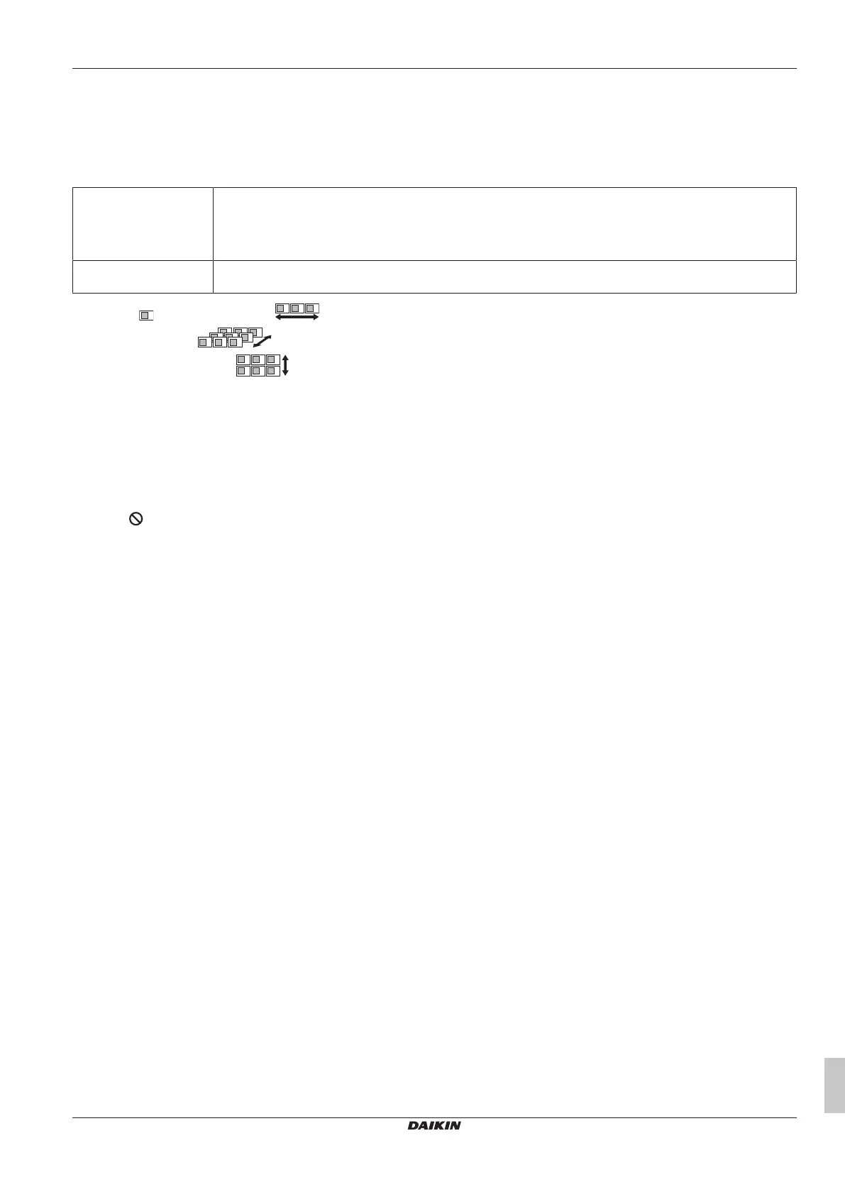
Single unit ( ) | Single row of units ( )
Multiple rows of units ( )
Stacked units (max. 2 levels) ( )
See figure 1 on the inside of the front cover.
(1) For better serviceability, use a distance ≥250mm
A,B,C,D Obstacles (walls/baffle plates)
E Obstacle (roof)
a,b,c,d,e Minimum service space between the unit and obstacles A, B, C, D and E
e
B
Maximum distance between the unit and the edge of obstacle E, in the direction of obstacle B
e
D
Maximum distance between the unit and the edge of obstacle E, in the direction of obstacle D
H
U
Height of the unit
H
B
,H
D
Height of obstacles B and D
1 Seal the bottom of the installation frame to prevent discharged air from flowing back to the suction side through the bottom of the unit.
2 Maximum two units can be installed.
Not allowed
See figure 2 on the inside of the front cover.
(1) For better serviceability, use a distance ≥250mm
See figure 3 on the inside of the front cover.
(1) For better serviceability, use a distance ≥250mm
A1=>A2 (A1) If there is danger of drainage dripping and freezing between the upper and lower units…
(A2) Then install a roof between the upper and lower units. Install the upper unit high enough above the lower unit to prevent ice buildup at the
upper unit's bottom plate.
B1=>B2 (B1) If there is no danger of drainage dripping and freezing between the upper and lower units…
(B2) Then it is not required to install a roof, but seal the gap between the upper and lower units to prevent discharged air from flowing back to the
suction side through the bottom of the unit.
 Loading...