Installation
Installation manual
7
RZAG71~140N7V1+Y1
Sky Air Alpha-series
4P573382-1 – 2019.04
B Distance between anchor points
C Bottom frame
D Drain holes
E Knockout hole for snow
Snow
In regions with snowfall, snow might build up and freeze between the
heat exchanger and the casing of the unit. This might decrease the
operating efficiency. To prevent this:
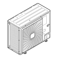
1 Remove the beam structure (see figure below).
2 Remove the knockout hole (a) by tapping on the attachment
points with a flat head screwdriver and a hammer.
3 Remove the burrs, and paint the edges and areas around the
edges using repair paint to prevent rusting.
NOTICE
Precautions when making knockout holes:
▪ Avoid damaging the casing and underlying piping.
▪ After making the knockout holes, we recommend to
remove the burrs and paint the edges and areas
around the edges using repair paint to prevent rusting.
▪ When passing electrical wiring through the knockout
holes, wrap the wiring with protective tape to prevent
damage.
INFORMATION
We suggest to install the optional bottom plate heater
(EKBPH140N7) when the unit is installed in cold climates.
4.1.4 To prevent the outdoor unit from falling
over
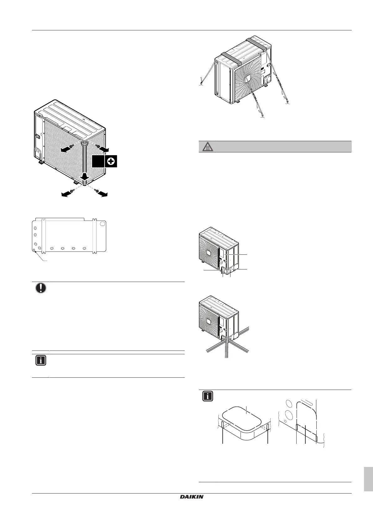
In case the unit is installed in places where strong wind can tilt the
unit, take following measure:
1 Prepare 2 cables as indicated in the following illustration (field
supply).
2 Place the 2 cables over the outdoor unit.
3 Insert a rubber sheet between the cables and the outdoor unit
to prevent the cables from scratching the paint (field supply).
4 Attach the ends of the cables and tighten them.
4.2 Connecting the refrigerant piping
DANGER: RISK OF BURNING
4.2.1 To connect the refrigerant piping to the
outdoor unit
▪ Piping length. Keep field piping as short as possible.
▪ Piping protection. Protect the field piping against physical
damage.
1 Do the following:
▪ Remove the service cover (a) with screw (b).
▪ Remove the piping intake plate (c) with screws (d).
2 Choose a piping route (a, b, c or d).
a Front
b Side
c Rear
d Bottom
INFORMATION
▪ Remove the knockout hole (a) in the bottom plate or
cover plate by tapping on the attachment points with a
flat head screwdriver and a hammer.
▪ Optionally, cut out the slits (b) with a metal saw.
 Loading...