IOM 1207-6 • TRAILBLAZER
®
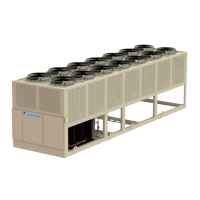
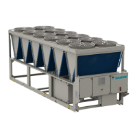
MODEL AGZ CHILLERS 114 www.DaikinApplied.com
Optional BAS Interface
The AGZ chiller controller is congured for stand-alone
operation or integration with BAS through an optional
communication module.
The appropriate installation manual for optional BAS interface
modules are shipped with the chiller. The current version of
each document can also be found and downloaded from www.
DaikinApplied.com.
• IM 966, BACnet
®
IP Communication Module
• IM 967, BACnet
®
Communication Module (MS/TP)
• IM 968, LONWORKS Communication Module
• IM 969, Modbus
®
Communication Module
Recommended Periodic Inspection
WARNING
Electrical Shock Hazard. Before servicing or inspecting
the equipment, disconnect power to the unit.The internal
capacitor remains charged after power is turned o. Wait
at least the amount of time specied on the drive before
touching any components.
Table 81: Periodic Inspection Checklist
Inspection Area Inspection Points Corrective Action
General
Inspect equipment
including wiring,
terminals, resistors,
capacitors, diode and
IGBT for discoloration
from overheating or
deterioration.
Replace damaged
components.
Inspect for dirt or foreign
particles
Use dry air to clear
away.
Relays and
Contactors
Inspect contactors and
relays for excessive
noise.
Check for over or
undervoltage
Inspect for signs of
overheating such as
melted or cracked
insulation
Replace damaged
parts.
Inverter Output to the Motor
WARNING
Avoid swapping any 2 of the 3 motor lead connections which will
cause reversal of the motor direction. In applications where reversed
rotation could cause equipment damage or personnel injury, be
sure to verify direction of rotation before attempting full-speed
operation. For safety to personnel, the motor chassis ground must
be connected to the ground connection at the bottom of the inverter
housing.
The AC motor must be connected only to the inverter’s
output terminals. The output terminals are uniquely labeled
(to dierentiate them from the input terminals) with the
designations U/T1, V/T2, and W/T3.
This corresponds to typical motor lead connection designations
T1, T2, and T3. The consequence of swapping any two of the
three connections is the reversal of the motor direction. This
must not be done. In applications where reversed rotation
could cause equipment damage or personnel injury, be sure to
verify direction of rotation before attempting full-speed
operation. For safety to personnel, the motor chassis ground
must be connected to the ground connection at the bottom of
the inverter housing.
Notice the three
connections to the
motor do not include
one marked “Neutral”
or “Return.” The motor
represents a balanced “Y”
impedance to the inverter,
so there is no need for
a separate return. In
other words, each of the
three “Hot” connections
serves also as a return
for the other connections
because of their phase
relationship.
Do not to switch o power to the inverter while the motor is
running (unless it is an emergency stop) to avoid equipment
damage. Also, do not install or use disconnect switches
in the wiring from the inverter to the motor (except thermal
disconnect).
 Loading...