www.DaikinApplied.com 41 IOM 1207-6 • TRAILBLAZER
®
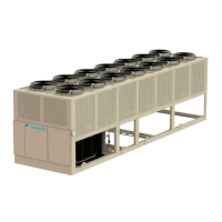
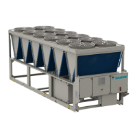
MODEL AGZ CHILLERS
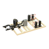
Figure 43: Typical Pump Package Layout
Factory-installed pump packages provide important benets:
• Simplify the chilled water system design and installation
• Provide installation savings by reducing eld piping,
wiring, and control costs
• Save valuable oor space inside the building
• Reduce project engineering content
• Greatly reduce pump operating cost with the optional
variable ow pump Variable Frequency Drive (VFD)
Standard Components of Pump
Packages
Figure 45 details the standard components included with a
factory mounted pump package as well as additional items that
may be factory mounted or eld supplied.
Pumps
Pump Design Features
1. Industry standard face mounted motor.
2. Flush and vent connection removes entrained air and
ensures liquid at seal face at all times.
3. Inside type mechanical seal with silicon carbide seat,
serviceable without breaking pipe connections.
4. Heavy cylindrical bracket with 360° register on both
anges provides a rigid union of pump and motor.
5. Dynamically balanced impeller assures smooth vibration-
free operation.
Figure 44: Pump Design Features
6. Radially split casing with equal suction and discharge
ange sizes. Separate tapped openings for gauge, ush,
and drain connections.
7. Liberal inlet passageways and straightening vanes
provide optimum suction performance and quiet
operation.
8. Ribs cast integral with casing. Machined surface to
accept oor support when specied.
9. Conned casing gasket to meet stringent industrial
temperature and pressure applications.
Vertical
Pump
Inlet
Strainer
Water
Inlet
Suction
Guide
VFD
Controllers
Chilled
Water
Outlet
Triple -Duty
Outlet Valve
Brazed -Plate
Evaporator
Evap In
Pressure Gauge/
Vent Ports
Evap Out
Flow Switch/
Temp Sensor/
Drain Ports
NOTE: Some refrigerant piping
removed for clarity of graphic.
Temp Sensor
Location
(back of evap)
Shut-off-
Butterfly Valve
Pressure Gauge
1
2
3
4
5
6
7
8
 Loading...