www.DaikinApplied.com 115 IOM 1207-6 • TRAILBLAZER
®
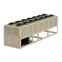
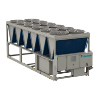
MODEL AGZ CHILLERS
Pump Start Control (MicroTech
®
III)
The standard arrangement is for the MicroTech
®
III unit
controller pump output signal to automatically start and stop
the pump(s). The methods and settings are discussed in See
Evaporator Pump Control on page 88.
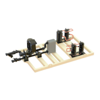
Details on pump package installation and application
considerations begin on page 41.
Pump VFD Operation
The VFD constantly monitors the chilled water system’s state.
When the building cooling load drops, air side controls will
start to close in order to control the space temperature. At that
instant in time, the pump power draw will start to drop. The
drive will notice this and slow down the pump (Hz output will
decrease) which then triggers a decrease in ow and head
since the pump impeller rpm is dropping.
The reverse is true when the load increases (valves open). The
power draw will increase and the drive will speed up (Hz goes
up) and the ow and head increases.
Both ow and head will uctuate and since they are being read
instantaneously, as opposed to an averaged value, even the
slightest change is registered on the screen.
A building’s cooling load tends to change slowly and it may be
dicult to discern load changes by merely observing the VFD
display. However, the pump rpm, Hz and kW can be noted over
time and used for reference. A given building load will have a
discrete reading.
Operating the VFD Controller
The VFD incorporates an integrated graphic local display and
keypad to select mode, change parameters and view status
and alarms.
The unit is shipped in the sensorless mode. If this mode is to
be used, no programming is required.
Control Functions
1. Graphical display with Status lines.
2. Menu keys and indicator lights (LED’s) - selecting mode,
changing parameters, and switching between display
functions.
3. Navigation keys and indicator lights (LEDs).
4. Operation keys and indicator lights (LEDs).
Figure 86: Graphical Local Control Panel (GLCP)
The LCD-display is back-lit with a total of 6 alpha-numeric
lines. All data is displayed on the LCP which can show up to
ve operating variables while in [Status] mode.
Status line (a): The status line is programmable with the
normal setup displaying hertz on the left, Pump kw in the
middle, and rpm on the right. Showing the status when in
status mode or up to two variables when not in status mode
and in the case of Alarm/ Warning. The number of the Active
Set-up (Sensorless mode being setup 1) is shown.
Data Lines (b): Operator data lines displaying data and
variables dened or chosen by the user. By pressing the
[Status] key, up to one extra line can be added. It shows up
to 5 variables with related unit regardless of status. In case of
alarm/warning, the warning is shown instead of the variables.
Normal setup is to show feet of head and gpm.
Status line (c): Status shows the state of the inverter such as
Run OK, Running on Auto Remote Running
Operating variables on the data lines (b) will vary depending on
the operating mode.
• Sensorless: displays gpm and head
• External Sensor: displays gpm and head
• BAS: congured by the BAS
• Hand: displays Hz
Status Display I
This read-out state is standard after start-up or initialization.
Status Display II
Use [INFO] to obtain information about the value/measurement
linked to the displayed operating variables (1.1, 1.2, 1.3, 2, and
3) shown in the display in Figure 87.
(a) Status Line
(b) Data Lines
(c) Status Line
 Loading...