17 | Configuration
Installer and user reference guide
73
VAM350~2000J8VEB
Heat reclaim ventilation unit
4P664012-1 – 2021.08
Mode SW SW description SW position
(a)
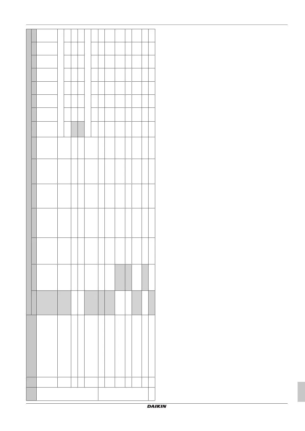
01 02 03 04 05 06 07 08 09 10 11 12 13 14 15
19(29) 0 Filter contamination inspection
(k)
Pressure-based
check with fan
step 1-15
Pressure-based
check with new fan
step
Timer based check Filter contamination
target detection with
fan step 1-15
Auto ESP selection
and filter
contamination
target detection
with new fan step
— — — — — — — — — —
1 Low tap
(l)
OFF Run 1/15 (28 min.
OFF/2 min. ON)
Run 1/10 (27 min.
OFF/3 min. ON)
Run 1/6 (25 min. OFF/5
min. ON)
Run 1/4 (22.5 min.
OFF/7.5 min. ON)
Run 1/3 (20 min.
OFF/10 min. ON)
Run 1/2 (15 min.
OFF/15 min.
ON)
Continuous operation
Step 1 Step 2 Step 3 Step 4 Step 5 Step 6 Step 7 Step 8
2 Supply fan step
(m)
Step 1 Step 2 Step 3 Step 4 Step 5 Step 6 Step 7 Step 8 Step 9 Step 10 Step 11 Step 12 Step 13 Step 14 Step 15
3 Exhaust fan step
(m)
Step 1 Step 2 Step 3 Step 4 Step 5 Step 6 Step 7 Step 8 Step 9 Step 10 Step 11 Step 12 Step 13 Step 14 Step 15
4 24-hour ventilation
(l)
OFF Run 1/15 (28 min.
OFF/2 min. ON)
Run 1/10 (27 min.
OFF/3 min. ON)
Run 1/6 (25 min. OFF/5
min. ON)
Run 1/4 (22.5 min.
OFF/7.5 min. ON)
Run 1/3 (20 min.
OFF/10 min. ON)
Run 1/2 (15 min.
OFF/15 min.
ON)
Continuous operation
Step 1 Step 2 Step 3 Step 4 Step 5 Step 6 Step 7 Step 8
19(29) 5 Humidification ON/OFF setting ON OFF — — — — — — — — — — — — —
7 Reference concentration shift for ventilation air flow
control (ppm)
0 +200 +400 +600 –200 –400 –600 — — — — — — — —
8 Stop ventilation by automatic ventilation air flow
control
Allowed NOT allowed Allowed NOT allowed — — — — — — — — — — —
8 Fan residual operation OFF OFF Heater operation Heater operation — — — — — — — — — — —
9 Normal ventilation tap on automatic ventilation air
flow control
— — — — Control by CO₂
sensor
— — — — — — — — — —
15 R32 safety system
(n)
OFF ON — — — — — — — — — — — — —
1A 0 Fresh-up operation
(k)
OFF ON — — — — — — — — — — — — —
(a)
Factory settings are marked with a grey background.
(b)
In case VAM and EKVDX are combined and the R32 safety system of the VAM is active, the nighttime free cooling is disabled.
(c)
The preheating/precooling function of the heat reclaim ventilation unit is disabled when it is connected to an EKVDX.
(d)
When connected to an EKVDX, set to 2 or 4.
(e)
When connected to an EKVDX, 17(27)-5 can be set to 1, 3, 4, 7 or 8.
(f)
(Supply air/Exhaust air), e.g. Low/Low means: Supply air low/Exhaust air low.
(g)
When connected to an EKVDX, JC/J2 cannot be used. Set to 18(28)-0-7. Instead, use T1 T2 of the EKVDX. See the EKVDX Installation and operation manual.
(h)
When connected to an EKVDX, do not change the default settings.
(i)
When connected to an EKVDX, JC/J1 cannot be used. Instead, use T1 T2 of the EKVDX. See the EKVDX Installation and operation manual.
(j)
When connected to an EKVDX, set to 18(28)-10-2.
(k)
When connected to an EKVDX, a filter contamination check is performed automatically and is timer based. This setting CANNOT be done with BRC301B61
(l)
When connected to an EKVDX, this field setting will always be OFF.
(m)
See the technical data book for pressure drop curves and selection of fan curves (step 1 to 15).
(n)
When connected to an EKVDX, setting 2 (safety ON) is required in case R32 refrigerant is used. Setting 1 (safety OFF) is required in case R410A refrigerant is used.
Note: When connected to an EKVDX, SS1 cannot be used. Instead, use T1 T2 of the EKVDX. See the EKVDX Installation and operation manual.
Note: The setting modes are mentioned as group settings, between parentheses are the setting modes for individual unit control or when connected to the EKVDX
option. Group number setting for central controller: mode 00=group controller / mode 30=individual controller. For the setting procedure, see "Group number
setting for central control" in the operation manual of either the ON/OFF controller or the central controller.



 To Next Page