17 | Configuration
Installer and user reference guide
72
VAM350~2000J8VEB
Heat reclaim ventilation unit
4P664012-1 – 2021.08
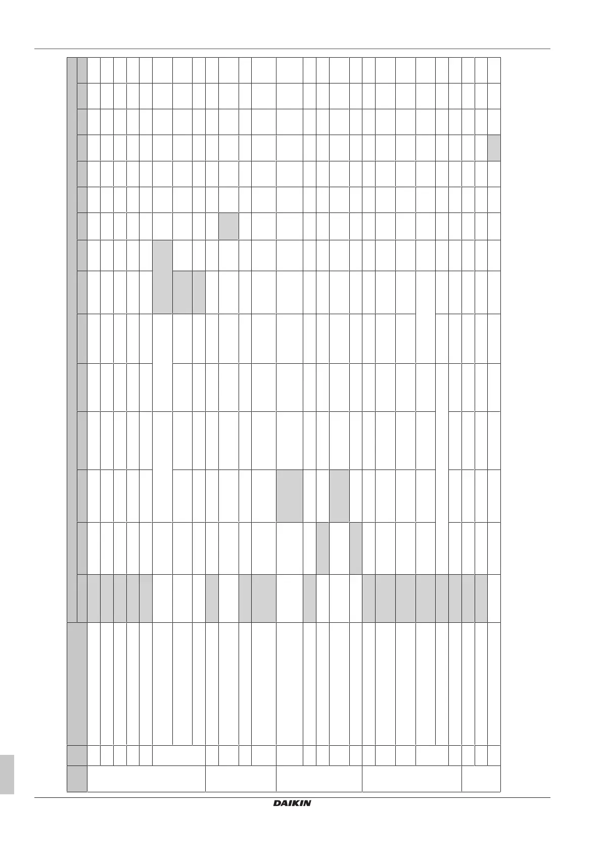
17.2 Field settings
Mode SW SW description SW position
(a)
01 02 03 04 05 06 07 08 09 10 11 12 13 14 15
17(27) 0 Filter cleaning time ±2500 hours ±1250 hours — — — — — — — — — — — — —
1 Nighttime free cooling timer (after stop)
(b)
OFF ON after 2hours ON after 4hours ON after 6hours ON after 8hours — — — — — — — — — —
2 Precool/preheat
(c)
OFF ON — — — — — — — — — — — — —
3 Precool/preheat duration
(c)
30 minutes 45 minutes 60 minutes — — — — — — — — — — — —
4 Initial fan speed
(d)
High Ultra-high — — — — — — — — — — — — —
5
(e)
Yes/No setting for duct connection with VRV system Without duct With duct Without duct With duct Without duct With
duct
— — — — — —
Setting for cold areas (fan operation when heater
thermostat is OFF)
(f)
— — Stop/Stop Low/Low Stop/stop Low/Low — — — — — — — — —
Fan operation during defrost/oil return/hot start
(f)
— — Stop/Stop Stop/Stop Stop/Stop Stop/Stop Stop/— Stop/Stop Stop/— — — — — — —
17(27) 6 Nighttime free cooling (fan settings)
(b)
High Ultra-high — — — — — — — — — — — — —
7 Target temperature for independent nighttime free
cooling
(b)
18°C 19°C 20°C 21°C 22°C 23°C 24°C 25°C 26°C 27°C 28°C 29°C 30°C — —
8 Central zone link No Yes — — — — — — — — — — — — —
9 Preheat time extension
(c)
0
minutes
30
minutes
60
minutes
90
minutes
— — — — — — — — — — —
18(28) 0 External signal
(g)
JC/J2 Last command Priority on external
input
Priority on operation Disable nighttime free
cooling/Perform forced
stop
— 24 hours
ventilation ON/OFF
Disable JC/J2 — — — — — — — —
1 Direct power ON OFF ON — — — — — — — — — — — — —
2 Auto restart
(h)
OFF ON — — — — — — — — — — — — —
3 Output signal to external damper (X24A) — — Damper output (fan
operation)
Damper output (fan
operation)
— — — — — — — — — — —
4 Indication of ventilation mode ON OFF — — — — — — — — — — — — —
18(28) 6 Automatic ventilation air flow mode Linear — Fixed A Fixed B — — — — — — — — — — —
7 Fresh-up mode Supply – no
indication
Exhaust – no
indication
Supply – indication Exhaust – indication — — — — — — — — — — —
8 External input terminal function selection
(i)
(JC/J1) Fresh-up Error output Error output and
stop operation
Forced off Fan forced off Air-flow up — — — — — — — — —
9 BRP4A50A output switching selection (between X3
and X4)
Heater output Error output Fan output (Low/
High/Ultra-high)
Fan output (High/Ultra-
high)
Fan output (Ultra-
high)
Fan output (Low/High/Ultra-high) — — — — — — — —
(between X1 and X2) Operation output Operation output — — — — — — — — — —
10 EKVDX connected?
(j)
No Yes — — — — — — — — — — — — —
18(28) 11 Filter contamination check No action Reset filter check Force filter check — — — — — — — — — — — —
13 Cooling set point (with EKVDX) 13°C 15°C 16°C 17°C 18°C 19°C 20°C 21°C 22°C 23°C 24°C 25°C 26°C 28°C 30°C
14 Heating set point (with EKVDX) 24°C 26°C 27°C 28°C 29°C 30°C 31°C 32°C 33°C 35°C 37°C 39°C 41°C 43°C 45°C



 To Next Page