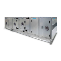
www.DaikinApplied.com 19 IM 915-13 • VISION - EXTENDED SIZES
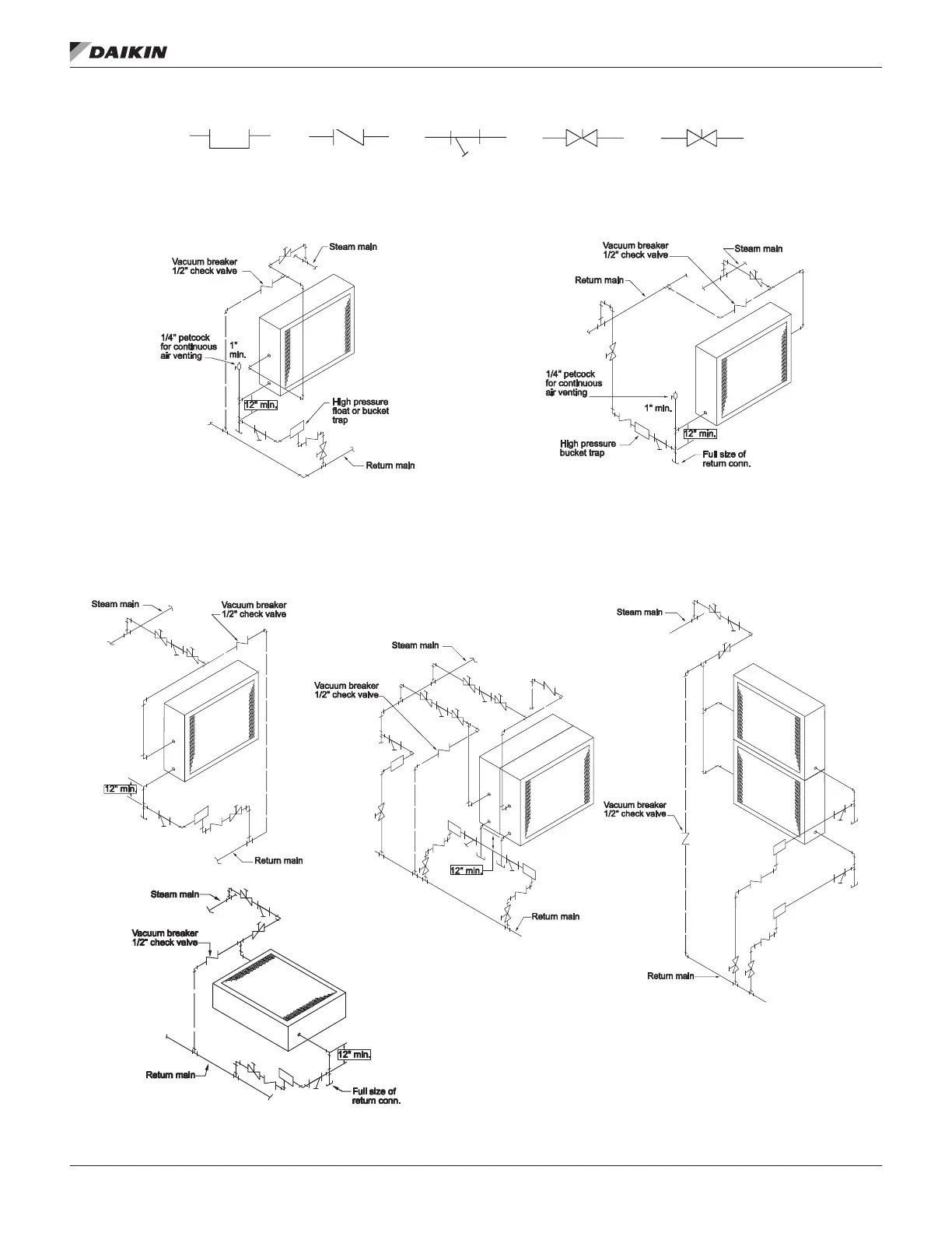
Figure 33: Piping Arrangements
Check Valve Strainer Gate Valve
Control valve
modulating
Float and
thermostatic trap
High Pressure (over 25 psi)
Low Pressure (to 25 psi)
5GA or 8GA coils. Note that the
addition of a vacuum breaker to
permit the coil to drain during
shutdown.
5TA, 8TA, or 5HA coils. Conden-
sate is lifted to overhead return
main
5JA or 8JA coil. Installed in series.
Note that each coil must have a
separate control valve and trap.
5RA, 8RA, or 5SA coils. Banked two
high, individual trapping of each coil as
shown is preferred.
5RA, 8RA, or 5SA coils. Installed
5J, 5G, 8J or 8G coils.