IM 915-13 • VISION - EXTENDED SIZES 22 www.DaikinApplied.com
The spring isolators under the four corners of the fan and
motor assembly are factory adjusted while the fan was not
running. See Table 1 through Table 4 below.
Table 1: Spring Mount Adjustments (Refer to Figure 37)
Spring mount adjustment at rest
Isolator
position
Top or bottom horz.
H (in.)
H (in.)
1 6.00 6.50
2 6.50 6.50
3 6.50 6.50
4 6.00 6.50
Table 2: Class II Belt-Drive Plenum Fan Spring Height
Fan Size Operating Height (in.)
18–36 4.0
40–60 6.75
Table 3: Class III Plenum Fan Spring Height
Operating Height (in.)
Width < 108" 4.0
Width >= 108" 6.75
Table 4: Class II Direct-Drive Plenum Fan Spring Height
Fan Size Operating Height (in.)
18–36 4.0
40–44 6.75
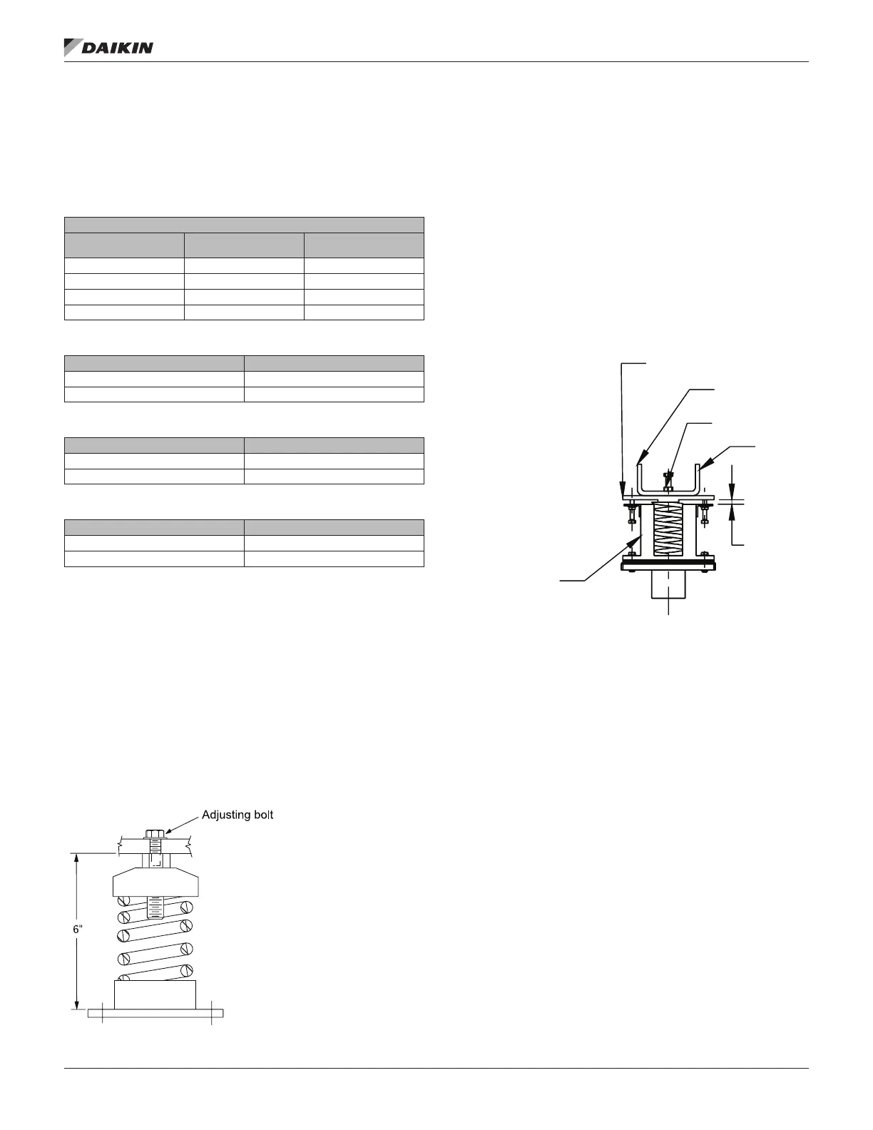
With the unit operating at normal cfm and static pressure,
all the isolators should be at the same height opening. If
adjustments are required, loosen the 1/2” cap screw on top of
the isolator and turn the adjusting bolt to lower or raise the fan
and motor base. Retighten the cap screw when adjustments
are completed.
The isolators should be at equal height during fan operation.
Center the fan outlet in the outlet panel opening. If adjustment
is required, loosen the cap screw on top of the isolator
assembly. Turn the adjustment nut below the fan frame to
lower or raise the fan motor and frame assembly. Retighten the
cap screw on top of the isolator assembly. See Figure 37.
Figure 37: Adjusting Spring Mount Assembly (Class 1 & 2)
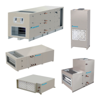
Before operation, Class 3 isolators should be adjusted as
follows:
1. Loosen the locknut on each of the four spring mount
assemblies
2. Adjust each the four leveling bolts in order to level the
fan assembly. The gap between each upper and lower
spring housing should be approximately 1/4”.
3. After all four springs are adjusted, tighten the locknut
located on each leveling bolt.
4. Turn the adjustable vertical restraint nuts until nger tight.
Figure 38: Adjusting Spring Mount Assembly (Class 3)
UPPER SPRING
HOUSING
BAS E
FAN
BOLT
LOCK NUT
L EVELING
NG
G
.2 5
FREE
HEIGHT