SiE39-404 Wiring Diagrams for Reference
Appendix 275
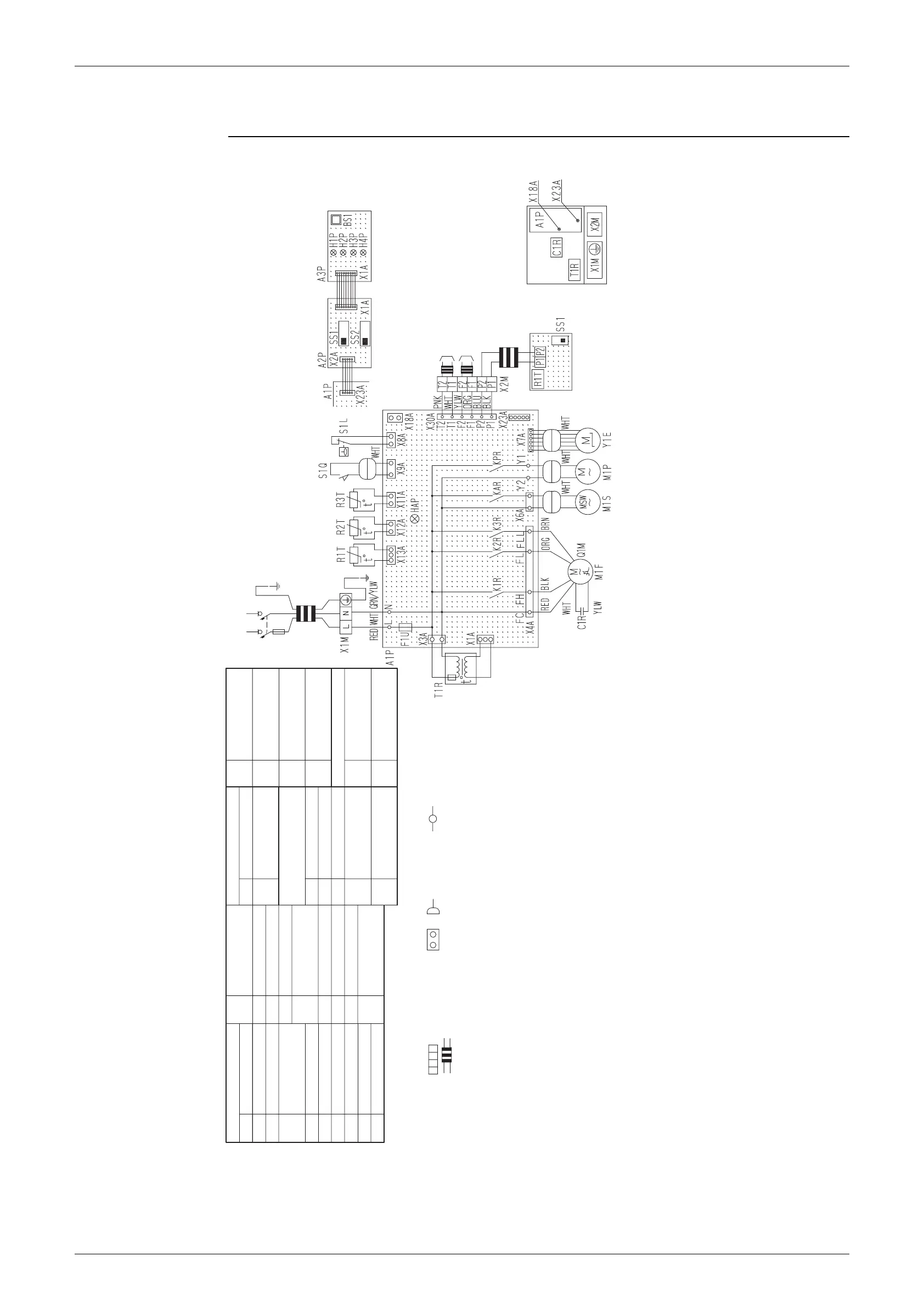
2.3 Indoor Unit
FXCQ20M / 25M / 32M / 63MVE
3D039556A
Notes
A1P
C1R
F1U
HAP
K1R-K3R
KAR
KPR
M1F
M1P
M1S
Printed circuit board
Capacitor (M1F)
Fuse (훾, 5A, 250V)
Light emitting diode
(Service monitor-green)
Magnetic relay (M1F)
Magnetic relay (M1S)
Magnetic relay (M1P)
Motor (Indoor fan)
Motor (Drain pump)
Motor (Swing flap)
Q1M
R1T
R2T•R3T
S1L
S1Q
T1R
X1M
X2M
Y1E
Thermo switch
(M1F embedded)
Thermistor (Air)
Thermistor (Coil)
Float switch
Limit switch
(Swing flap)
Transformer (220-240V/22V)
Ter minal block (Power)
Ter minal block (Control)
Electronic expansion
valve
Indoor unit
R1T
SS1
Thermistor (Air)
Selector switch
(Main/Sub)
A2P
A3P
BS1
H1P
H2P
Printed circuit board
Printed circuit board
Push button (On/off)
Light emitting diode
(On-red)
Light emitting diode
(Timer-green)
Infrared remote control
Receiver/display unit
(Attached to
infrared remote control)
1. : Terminal block, , : Connector, : Terminal
2. : Field wiring
3. In case using central remote control, connect it to the unit in accordance
with the attached instruction manual.
4. X23A is connected when the infrared remote control kit isbeing used.
5. When connecting the input wires from outside, forced off or on/off control
operation can be selected by remote control.
In details, refer to the installation manual attached the unit.
6. Symbolsshowsas follows.
(PNK: pink, WHT: white, YLW: yellow, ORG: orange, BLU:
blue, BLK: black,
RED: red, BRN: brown, GRN: green)
H3P
H4P
SS1
SS2
Light emitting diode
(Filter sign-red)
Light emitting diode
(Defrost-orange)
Selector switch
(Main/sub)
Selector switch
(wireless address set)
X18A
X23A
Connector
(Wiring adaptor for
electorical appendices)
Connector
(Infrared remote
control)
Connector for optional parts
Power supply
Note 4 Receiver/display unit
(Infrared remote control)
Note 5
Input from outside
Note 3
Transmission wiring
central remote control
Note 4
Infrared remote control
(Optional accessory)
Electric partsbox
220-240V
~
50Hz
220V
~
60Hz

 Loading...