9 Relocation
Installation and operation manual
15
RXYSQ4~6T8V/YB(*)
VRV IV-S system air conditioner
4P482275-1B – 2020.10
8.2.16 Symptom: The compressor in the outdoor
unit does not stop after a short heating
operation
This is to prevent refrigerant from remaining in the compressor. The
unit will stop after 5 to 10 minutes.
8.2.17 Symptom: The inside of an outdoor unit is
warm even when the unit has stopped
This is because the crankcase heater is warming the compressor so
that the compressor can start smoothly.
8.2.18 Symptom: Hot air can be felt when the
indoor unit is stopped
Several different indoor units are being run on the same system.
When another unit is running, some refrigerant will still flow through
the unit.
9 Relocation
Contact your dealer for removing and reinstalling the total unit.
Moving units requires technical expertise.
10 Disposal
This unit uses hydrofluorocarbon. Contact your dealer when
discarding this unit.
NOTICE
Do NOT try to dismantle the system yourself: dismantling
of the system, treatment of the refrigerant, oil and other
parts MUST comply with applicable legislation. Units
MUST be treated at a specialised treatment facility for
reuse, recycling and recovery.
For the installer
11 About the box
11.1 About
is part of Daikin's wider commitment to reduce our
environmental footprint. With we want to create a circular
economy for refrigerants. One of the actions to achieve this, is the
reuse of reclaimed refrigerant in VRV units produced and sold in
Europe. For more information about the countries that are in scope,
visit: http://www.daikin.eu/loop-by-daikin.
11.2 Outdoor unit
11.2.1 To remove the accessories from the
outdoor unit
1 Remove the service cover. See "To open the outdoor
unit"[416].
2 Remove the accessories.
3 Remove the service cover. See "To open the outdoor
unit"[416].
4 Remove the accessories.
a General safety precautions
b Outdoor unit installation and operation manual
c Fluorinated greenhouse gases label
d Multilingual fluorinated greenhouse gases label
e Gas piping accessory 1 + copper gasket (only for
RXYSQ6)
f Gas piping accessory 2 (only for RXYSQ6)
g Gas piping accessory 3 (only for RXYSQ6)
12 About the units and options
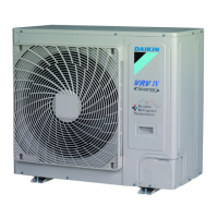
12.1 About the outdoor unit
This installation manual concerns the VRV, full inverter driven, heat
pump system.
These units are intended for outdoor installation and aimed for air to
air heat pump applications.
Specification RXYSQ4~6
Capacity Heating 14.2~18.0kW
Cooling 12.1~15.5kW
Ambient design
temperature
Heating –20~15.5°CWB
Cooling –5~46°CDB
12.2 System layout
NOTICE
Design of the system must not be done at temperatures
below –15°C.
a VRV IV-S Heat pump outdoor unit
b Refrigerant piping
c VRV direct expansion (DX) indoor unit
d User interface (dedicated depending on indoor unit type)
e BP box (required to connect Residential Air (RA) or Sky Air
(SA) direct expansion (DX) indoor units)
f Residential Air (RA) direct expansion (DX) indoor units
g User interface (wireless, dedicated depending on indoor
unit type)
 Loading...


