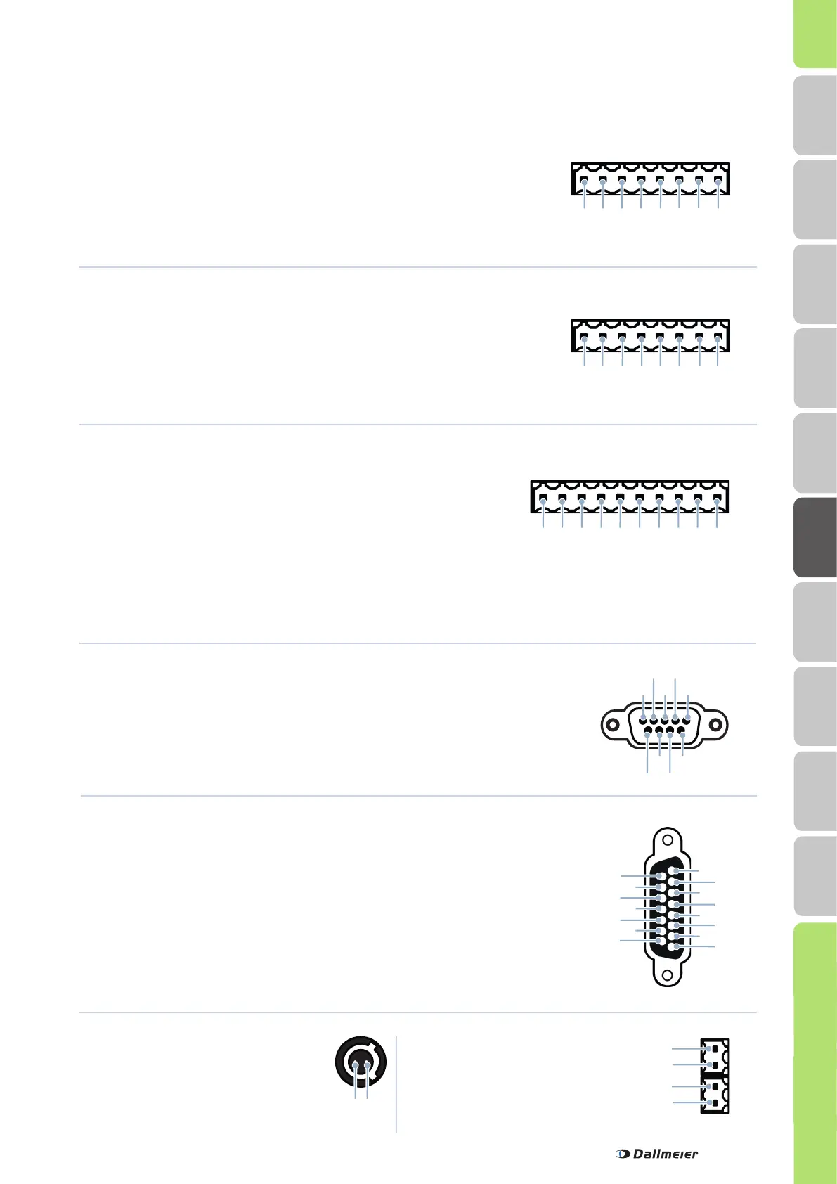
Serial interface (B)
2× Weidmüller, 2 pins
Pin Assignment
1 RS485 / TX+
2 RS485 / TX-
1
2 3 4 5 6 7 8
1 2 3 4 5 6 7 8 9 10
2
1
1 2
4
3
Pin Assignment
3 RS485 / RX+
4 RS485 / RX-
9
DMS 2400
Assignment of the sockets
Relay OUT (F)
Weidmüller, 10 pins
Contact IN global (C)
Weidmüller, 8 pins
Contact IN cameras (A)
Weidmüller, 8 pins
Pin Assignment
1 GND
2 Contact 1
3 Contact 2
Pin Assignment
4 Contact 3
5 Contact 4
6 Contact 5
Pin Assignment Triggering event Type
1 + 2 Relay 1 Recorder in alarm state Normally open
3 + 4 Relay 2 None Normally open
5 + 6 Relay 3 System error Normally closed
7 + 8 Relay 4 None Normally open
9 + 10 Relay 5 More than 80 % of the
secure tracks occupied
Schließer
12V DC OUT (U)
ODU socket, 2 pol
Pin Assignment
1 12 V DC
2 GND
Pin Assignment
7 Contact 6
8 GND
Pin Assignment
1 GND
2 Contact 1
3 Contact 2
Pin Assignment
4 Contact 3
5 Contact 4
6 Contact 5
Pin Assignment
7 Contact 6
8 GND
Pin Assignment
1 Audio 1
2 Audio 2
3 Audio 3
4 Audio 4
5 Audio 5
Pin Assignment
6 Audio 6
7 Audio 7
8 Audio 8
9 GND 1
10 GND 2
Pin Assignment
11 GND 3
12 GND 4
13 GND 5
14 GND 6
15 GND 7 + 8
Audio IN (T)
D-SUB, 15-polig, ohne D-SUB/Cinch Adapterkabel
Serial interface (I and R)
D-SUB, 9 pins
Pin Assignment
1 DCD
(Data Carrier Detect)
2 RxD (Receive Data)
3 TxD (Transmit Data)
Pin Assignment
4 DTR
(Data Terminal Ready)
5 GND
6 DSR
(Data Set Ready)
Pin Assignment
7 RTS
(Request to Send)
8 CTS (Clear to Send)
9 RI (Ring Indicator)
1 2 3 4 5 6 7 8
6
1
5
4
3
2
9
8
7
15
10
8
3
1
2
4
5
6
7
9
11
12
13
14
HDD Mounting
Mounting
Safety
Requirements
DLS 1600
Local Login
Dimensions
DMS 2400
Remote Login Indicators