AK-PC 551 User Guide RS8GY302 © Danfoss 2015-06 23
Connections
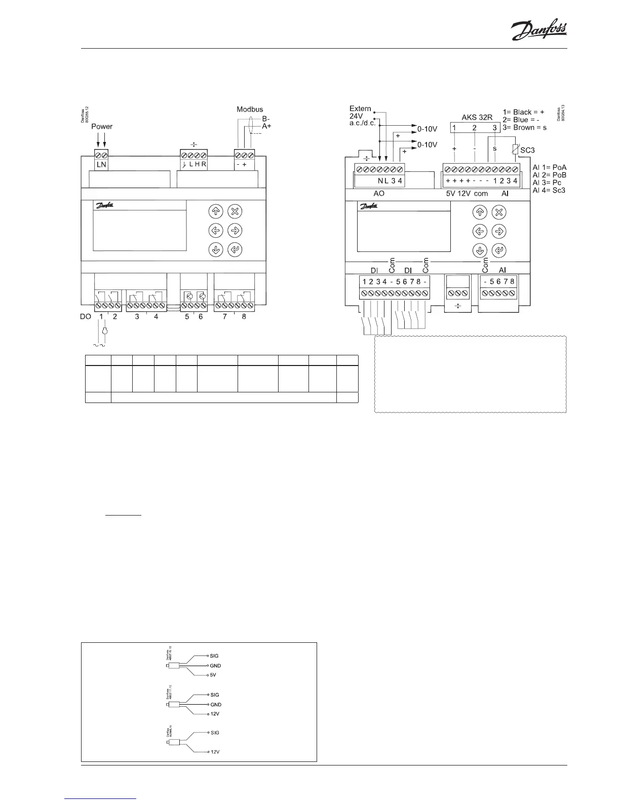
DO DO1 DO2 DO3 DO4 DO5 DO6 DO7 DO8 Σ 1-8
I Max. 10 A
(3.5)
10 A
(3.5)
6 A
(4)
6 A
(4)
0.5 A
min. 50 mA
Io < 1,5 mA
0.5 A
min. 50 mA
Io < 1,5 mA
6 A
(4)
6 A
(4)
32 A
U All 24 V or all 230 V a.c.
AKS 32
AKS 33
AKS 32R
Connection, lower level Connection, upper level
Supply Voltage.
The supply voltage is either 24 V or 110-230 V. See the label on
the reverse side of the controller.
÷ = Plugs normally not used
However, if connecting to an external display, a jumper must
be inserted between the connections "H" and "R".
Modbus
It is important that the installation of the data communication
cable be done correctly. Cf. separate literature No. RC8AC.
Remember termination at the bus termination.
DO - Digital outputs, 8 pcs. DO1 - DO8
DO5 and DO6 are solid state relays.
The relays are de-rated to the specied values.
If an alarm relay is dened, it will be driven under normal op-
eration and it will drop in the event of alarms and insucient
power to the controller.
AO - Analogue output, 2 pcs. AO3 - AO4
Must be used when using a frequency converter or EC motors.
Connect 24 V on N and L (separate supply). Avoid earth fault
current. Use double-insulated transformer. The secondary side
must not be earthed.
Obtain 0-10 volts from terminals N and AO3, respectively N and
AO4. PAY ATTENTION TO THE POLARITY of N.
AI - Analogue inputs, 4 pcs. AI1 - AI4
Pressure transmitters
• Ratiometric: 10-90% of supply, AKS 32R
• Signal: 1-5 V, AKS 32
• Power: 0-20 mA / 4-20 mA, AKS 33 (supply = 12 V)
Temperature sensor
• Pt 1000 ohm, AKS 11 or AKS 21.
• NTC 86K ohm @ 25°C, from digital scroll.
Factory settings
AI1=PoA, AI2=PoB, AI3=Pc, AI4=Outdoor temperature SC3.
DI - Digital switch inputs, 8 pcs. DI1 - DI8
The connection may be a shut-down or interruption function.
Select what is to be activated during conguration.
÷ = Plugs normally not used
AI - Analogue inputs, 4 pcs. AI5 - AI8
Pressure transmitters
• Ratiometric: 10-90% of supply, AKS 32R
• Signal: 1-5 V, AKS 32
Temperature sensor
• Pt 1000 ohm, AKS 11 or AKS 21.
• NTC 86K ohm @ 25°C, from digital scroll
10-90% ratiometric
1-5 V
0-20mA
4-20mA
Warning
The supply voltage of AI may not share
the signal with other controllers.
Separate
supply!
Electric noise
Signal cables for sensors, DI inputs, data communication
and display must be kept separate from high voltage
(230 V) electric cables:
- Use separate cable trays
- Keep a distance between high voltage and signal cables
of at least 10 cm
- Cables longer than 3 m at the DI input should be avoided