User Guide | Optyma™ control AK-RC 111 single phase
14 | BC309238530328en-000101 © Danfoss | DCS (vt) | 2020.03
7.0 Appendices
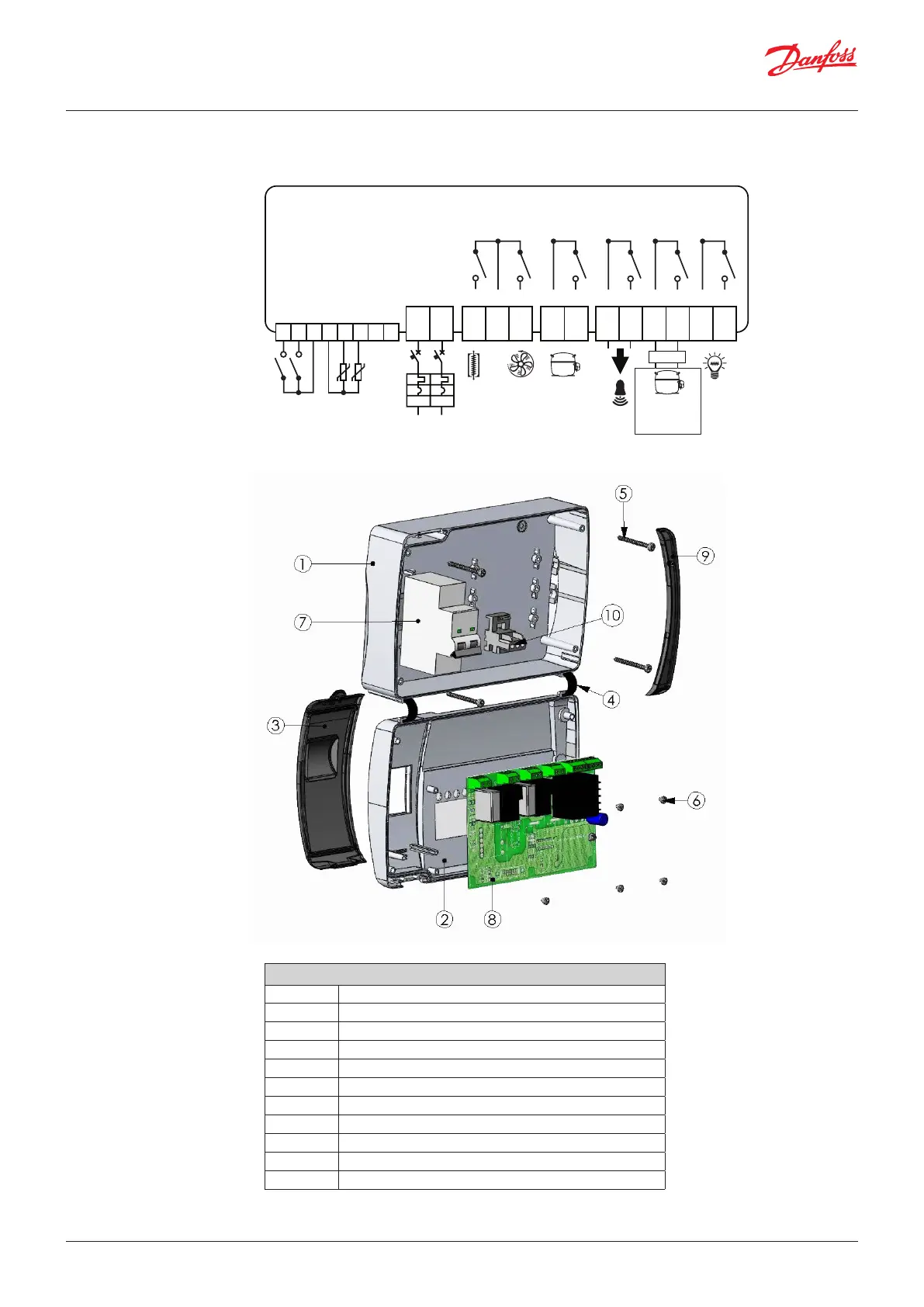
7.1 AK-RC 111 wiring diagram
7.2 Part List
Key
Ref. Description
1. Box rear in Abs
2. Box front in Abs
3. Front cover in transparent polycarbonate
4. Box front opening hinge
5. Box closure screws
6. Board fixing screws
7. Magneto-thermal cut-out / power breaker
8. CPU board
9. Polycarbonate screw cover
10. Terminal for earth connections
N
F
/d /d
1 2 3 4 5 6 7 8
9 10 11 12 13 14 15 16 17 20 21 18 19
MODBUS B-
Power
Supply
230 V AC
Defrost Fans Compr. Aux1/All.
Condensing
unit
Electric
switchboard
enable
Aux2 Light
MODBUS A+
Defrost probe
Ambient probe
Common probes
Common dig. inputs
Digital input 2
Digital input 1
Common
 Loading...