User Guide | Optyma™ control AK-RC 111 single phase
© Danfoss | DCS (vt) | 2020.03 BC309238530328en-000101 | 5
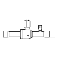
Fig 5. Press on the sides of the hinges to remove them from
their seats and so remove the front panel completely.
Fig 6. Use the three existing holes to fix the box back panel
to the wall: use three screws of a length suitable for the
thickness of the wall to which the panel will be attached.
Fit a rubber washer (supplied) between each screw and the
box backing.
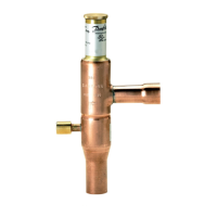
Fig 7. Hook the frontal panel back up to the lower part
of the box by inserting the two hinges in their seats and,
bending them, rotate downwards 180° to gain access to
the electronic board.
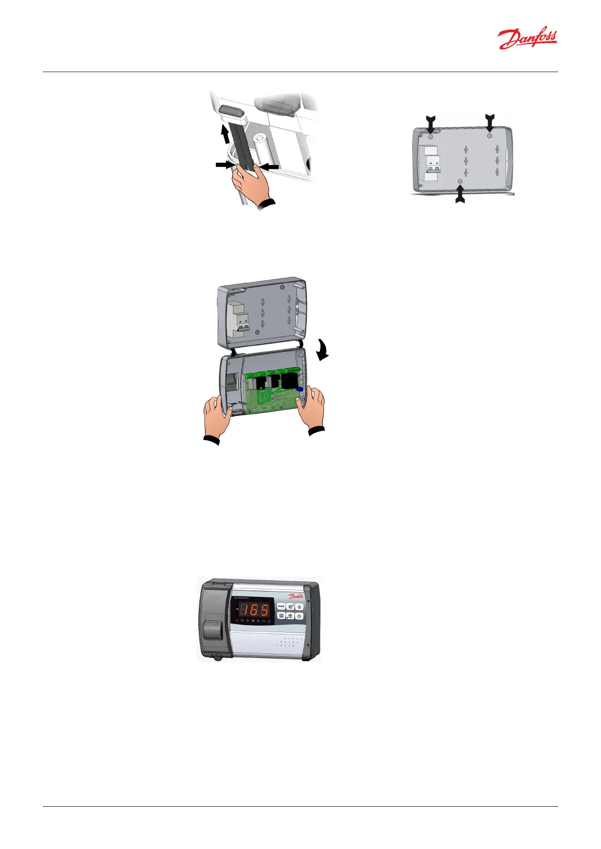
Fig 8. Close the front panel, making sure that all the wires
are inside the box and that the box seal sits in its seat
properly. Tighten the front panel using the 4 screws.
Power up the panel and carry out thorough reading/
programming of all the parameters.
Note: Make all the electrical connections as illustrated in the diagram for the corresponding model
(see relative table in appendices). To make electrical connections reliably and maintain the protection
rating, use appropriate cable glands and pipepresses to ensure a good seal. It is advisable to distribute
the passage of the conductors inside the panel as far as possible, in particular to keep the power leads
away from the cables of the signal. Use clips to hold wires in place.
Note: Be careful not to over-tighten the closure screws as this could warp the box and compromise
proper operation of the membrane-type keypad. Install short-circuit overload safety devices on all
the power cables connected to the AK-RC 111 so as to prevent damage to the device. Work and/or
maintenance must ONLY be carried out on the unit after disconnecting the panel from the power
supply and from any inductive/power loads: doing so allows the worker to do his job safely.
 Loading...