10 Function description RC.1J.Z4.02 © Danfoss 09/1999 AKC 25H1
Example:
A system consists of three condenser steps. Here the definition can be made, as follows:
Output Configuration DO Relay No. ( ) DO5 Ttype = 2 (2=condenser)
DO5 Dev. No = 2
DO6 Type = 2 (2=condenser)
DO6 Dev. No = 1
DO9 Type = 2 (2=condenser)
DO9 Dev. No = 3
Here the cut in and cut out sequence will be, as follows: 1, 2, 3 - 3, 2, 1.
I.e., the relay outputs will be activated in this sequence: DO6, DO5, DO9 - DO9, DO5, DO6.
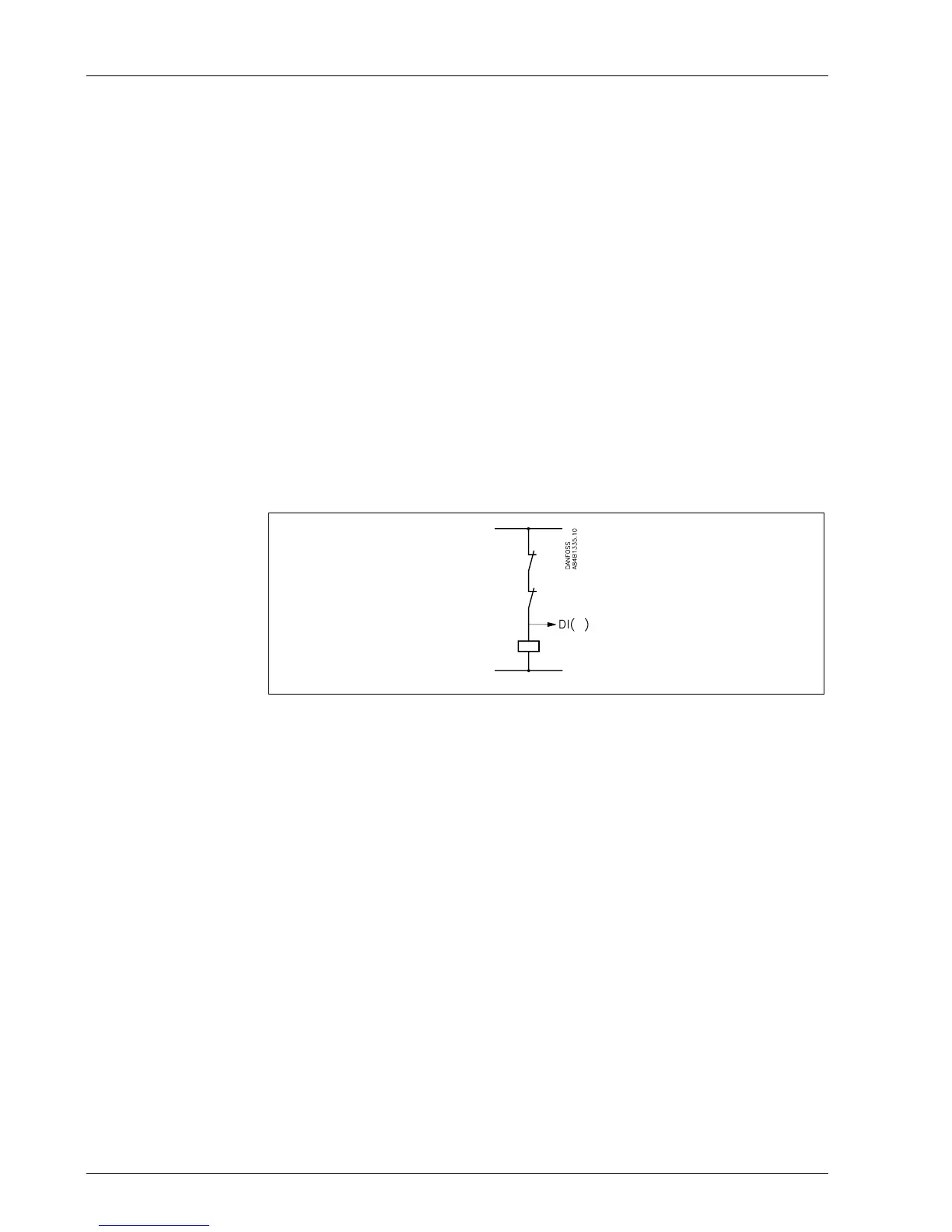
Signal from the condenser's safety controls
The controller can receive signals on the status of each condenser step’s safety circuit. The
signal is taken directly from the safety circuit and is connected to a “DI” input.
This input is a 230 V a.c. input.
If the safety circuit is broken, the controller will cut out the output relay for the relevant step
and give an alarm. The remaining steps will continue the regulation. (A broken connection on
the DI input will cut out the output).
An input from a condenser step and the number of the condenser step are defined.
Input Configuration Alarm input No. 1..9 DI( ) Type = 2 (2= condenser)
DI( ) Dev. No. ___
A time delay must be defined for the period from the alarm is registered until it is transmitted.
Input Configuration Alarm input No. 1..9 DI( ) Del. m ___
Hourmeter
The run time of the different outputs is registered by a counter. This registration can be
displayed and reset, if required.
Output Configuration DO Relay No.( ) DO( ) Time h
The hourmeter’s range is from 0 to 30,000 hours.
Forced control of condenser capacity
Forced control of the capacity can be arranged, where the normal regulation is disregarded.
The capacity is set in per cent of the regulated capacity.
Condensor Capacity ctrl. Settings Condenser ctrl. Man. Cap OFF/ON
Man. Cap. % ___
Condenser control, but no compressor control
The controller is normally used for controlling both compressors and condensers. If the
controller is only used for controlling condensers, a missing signal from pressure transmitter
input PO will trigger an alarm signal. To avoid this alarm, a signal may be picked up from
pressure transmitter Pc. Connect terminal 72 to 76 (“s” to “s”). The monitoring function for
POmin is now set at the lowest possible value.
 Loading...


