AKC 25H1 Function description RC.1J.Z4.02 © Danfoss 09/1999 7
Sequence for cut in and cut out of capacity
The sequence for cut in and cut out of capacity can be defined in two ways. Either with a fixed
defined sequence or with automatic equalisation of run time between the connected
compressors. The sequence will be established by the following setting:
1. Sequential (Step Mode = 1).
In general the numbers with which the different compressors are defined will establish the
sequence for the cut ins (the compressor defined with a low number will start before a
compressor with the next number).
The sequence for the cut outs will furthermore be established by the compressor type:
Compressors with one step
The sequence is not changed (last cut in step will be cut out first, when the required
capacity drops again).
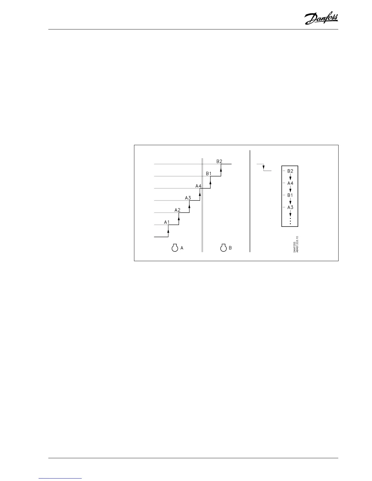
Compressors with several steps
When there are cut outs, the steps on the borderline between the two compressors will
be changed around. The function will produce the effect that the last started compressor
will not stop until the control has cut out the “last” step of the previous compressor.
Example:
Cut in Cut out
2. Automatic equalisation of run time between compressors (Step Mode = 2).
This setting should only be used if capacities of the same size are cut in or out but it is not a
requirement. (Regulation can also be carried out on compressors with several steps).
- At the different starts, the compressor with the lowest amount of run time will be started
first.
- At the different stops, the compressor with the highest amount of run time will be stopped
first.
- For compressors with several steps there will be no changes of the steps, as is the case
with sequential cut ins and cut outs.
Compressor Capacity Ctrl. Settings Compressor ctrl. Step Mode 1 / 2
Signal from the compressor's safety controls
The controller requires a signal on the status of each compressor’s safety circuit. The signal
taken directly from the safety circuit is connected to a “DI” input. This input is a 230 V a.c.
input.
(The safety circuit must stop the compressor without the help of AKC 25H1).
If the safety circuit is broken, the controller will cut out all output relays for the compressor in
question and give an alarm. The other compressors will continue the regulation. (A broken
circuit at the DI input cuts out the outputs).
An input from a compressor and the compressor’s number are defined.
Input Configuration Alarm input No. 1..9 DI( ) Type = 1(1=compressor)
DI( ) Dev. No. ___ (compressor No.)
A time delay has to be defined in connection with all alarms. It covers the period of time from
the cut out moment until the alarm is registered.
Input Configuration Alarm input No. 1..9 DI( ) Del. m ___
 Loading...


