73695050 DH-SMT/SI VI.DB.T3.3F © Danfoss 02/2011 7
ENGLISH
Safety Notes
Prior to assembly and commissioning to
avoid injury of persons and damages of
the devices, it is absolutely necessary
to
carefully read and observe these instructions.
Necessary assembly, start-up, and
maintenance work must be performed
only by qualified, trained and authorized
personnel.
Prior to assembly and maintenance work
on the controller, the system must be:
- depressurized,
- cooled down,
- emptied and
- cleaned.
Please comply with the instructions of the
system manufacturer or system operator.
Definition of Application
The controller is in combination with
electrical actuators (AMV(E) used for flow
and temperature control of water and
water glycol mixtures for heating, district
heating and cooling systems.
AVQM PN 16 could be combined with
electrical actuators AMV(E) 10/13 (DN15
only), AMV(E) 20/23, AMV 20/23 SL,
AMV(E) 30/33, AMV 30, AMV 150.
AVQM(T) PN 25 could be combined
with electrical actuators AMV(E) 10/13
(DN15 only), AMV(E) 20/23, AMV 20/23 SL,
AMV(E) 30/33, AMV 30, AMV 150.
AVQMT PN 25 could be combined with
temperature actuator AVT or safety
temperature monitor (actuator) STM.
The technical parameters on the product
labels determine the use.
Assembly
Admissible Temperatures ❶
Admissible Installation Positions ❷
Medium temperatures up to 100 °C:
- Can be installed in any position,
except
with electrical actuator oriented
downwards.
Medium temperatures > 100 °C:
- Installation permitted only in horizontal
pipelines with the electrical actuator
oriented upwards.
Other details:
See instructions for electrical actuator
AMV(E). In case of AVQMT controller see
instructions for temperature actuator AVT
or safety temperature monitor (actuator)
STM as well.
Installation Location and
Installation Scheme
AVQM(T) return mounting ❸
AVQM(T) flow mounting ❹
Valve Installation ❺
1. Clean pipeline system prior to assembly.
2. The installation of a strainer ① in
front of the controller is strongly
recommended.
3. Install valve
• The flow direction indicated on the
product label ② or on the valve ③
must be observed.
• The valve with mounted weld-on
tailpieces may only be spot welded to
the pipeline ④.
The weld-on tailpieces may be welded
only without the valve and seals! ⑤⑥
If these instructions are not observed,
high welding temperatures may
destroy the seals.
• Flanges ⑦ in the pipeline must be in
parallel position and sealing surfaces
must be clean and without any
damage.
Tighten screws in flanges crosswise
in 3 steps up to the maximum torque
(50 Nm).
4. Caution:
Mechanical loads of the valve body by the
pipelines are not permitted ⑧.
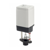
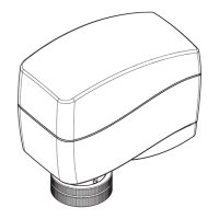
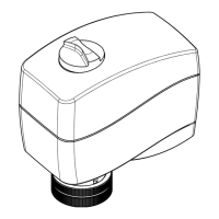
Mounting of electrical actuator ❻
Place electrical actuator AMV(E) on the
valve and tighten union nut with wrench
SW 32.
Torque 25 Nm.
Other details:
See instructions for electrical
actuator AMV(E).
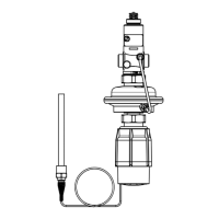
Mounting of temperature
actuator ❼
(relevant only at AVQMT controllers)
Place temperature actuator AVT or STM at
the diaphragm and tighten union nut with
wrench SW 50.
Torque 35 Nm.
Other details:
See instructions for temperature
actuator AVT or STM.
Insulation ❽
For medium temperatures up to 100 °C the
pressure actuator ① may also be insulated.
Insulation of electrical actuator ②
AMV(E) is not allowed.
Dimensions, Weights ❾
1)
Conical ext. thread acc. to EN 10226-1
2)
Flanges PN 25, acc. to EN 1092-2
3)
Other flange dimensions – see table
T1
for tailpieces.
Start-up ❿
Filling the system, first start-up
1. Open valves in the system.
2. Slowly open shut-off devices ① in the
flow pipeline.
3. Slowly open shut-off devices ② in the
return pipeline.
Leak and Pressure Tests
Do not test closed control valve with
pressures of more than 16 bar. Otherwise,
the valve may be damaged.
Pressure tests should be carried out prior
to the installation of the electrical actuator.
This guarantees that the valve is opened.
Before pressure test, open the adjustable
flow restrictor ④⑤ by turning it:
- at PN 16 controller to the left (counter
clockwise) ⑥
- at PN 25 controller to the left
(counter clockwise) ⑦ or to the right
(clockwise) ⑧
Pressure must be gradually
increased at the (+/-)
connection ③.
Non-compliance may cause damages at
the actuator or the valve.
A pressure test of the entire system
must be carried out in accordance with
manufacturer’s instructions.
The maximum test pressure is: 1.5 × PN
PN – see product label!
Putting out of operation
1. Slowly close shut-off devices ① in the
flow pipeline.
2. Slowly close shut-off devices ② in the
return pipeline.
 Loading...